Magnetic connector

A technology of magnetic connectors and magnetic components, which is applied in the direction of connection, parts of connection devices, contact parts, etc., can solve the problems of difficult movement, complex structure, inconvenient processing, etc., and achieve convenient connection, low processing cost, and convenient processing Effect

Active Publication Date: 2018-11-16
廖芳
View PDF7 Cites 0 Cited by
  • Summary
  • Abstract
  • Description
  • Claims
  • Application Information

AI Technical Summary

Problems solved by technology

[0002] The magnetic connectors in the prior art include male and female connecting units, both of which include a plastic body, contact pins, plastic brackets for the contact pins, and exposed magnetic blocks. The male connecting unit also includes concentric contact terminals, and the female connecting unit probes At the contact end, the male and female connection units are combined together by the suction force of the magnetic block, and are equipped with a fool-proof design. This technical means realizes the accurate positioning of the connector and is not easy to move after connection, the connection is firm, and it is also very convenient to disassemble. Complex structure, inconvenient processing and high cost

Method used


Image

  • Magnetic connector
  • Magnetic connector
  • Magnetic connector

Examples


Embodiment 1

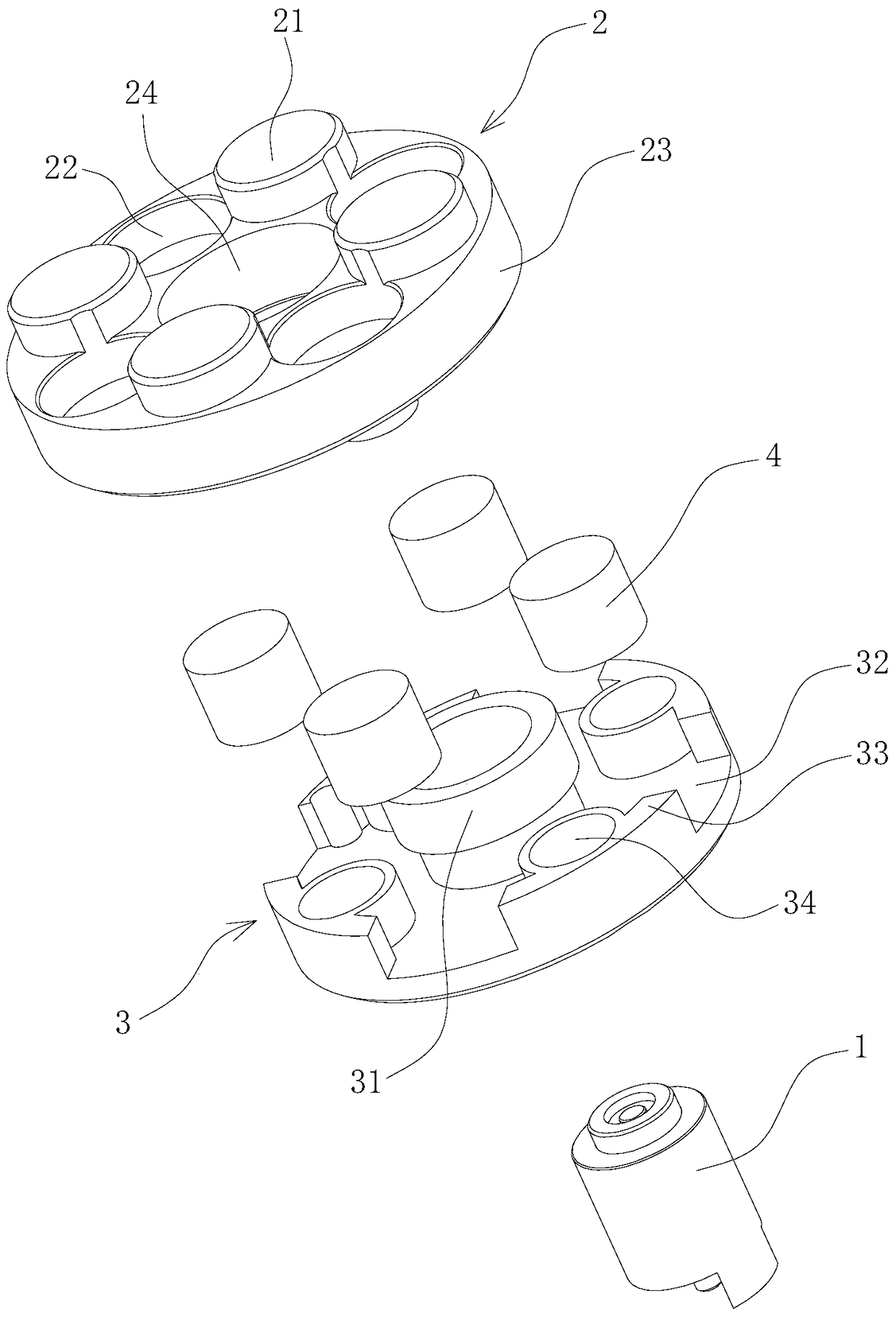
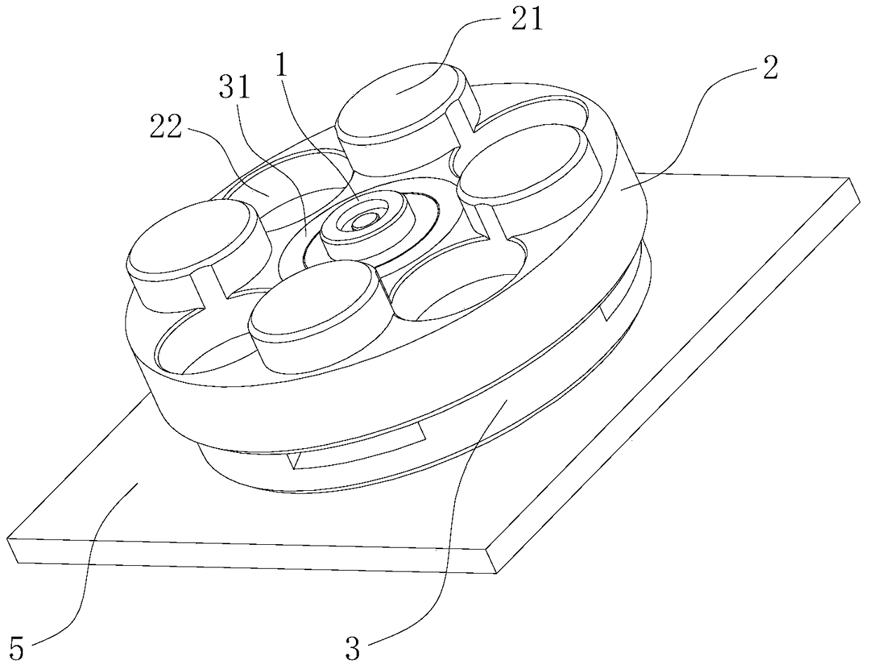
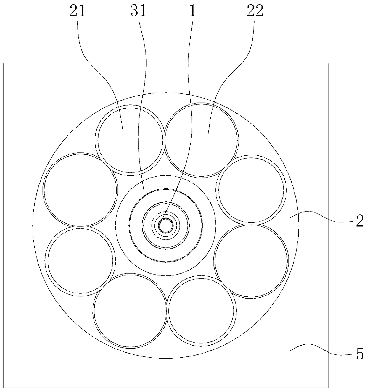
[0027] Figure 1 to Figure 5 A magnetic connector according to one embodiment of the present invention is schematically shown.

[0028] refer to Figure 1 ~ Figure 3 , The magnetic connector includes a concentric contact terminal 1, an insulating component 3 and a conductive magnetic component composed of a magnetically attractive metal end cap 2 and a magnet 4. The magnetic metal end cap 2 is fastened and fixedly connected with the insulating component 3 by clamping or threading. The concentric contact terminal 1 runs through the magnetic metal end cap 2 , and an insulating component 3 is provided between the concentric contact terminal 1 and the magnetic metal end cap 2 . The magnet 4 is located inside the magnetic metal end cap 2 , and can also be directly bonded or fixed outside the magnetic metal end cap 2 in other ways. The projected area of ​​the magnet 4 on the cross-section of the magnetic metal end cap 2 is less than half of the cross-sectional area of ​​the magne...

Embodiment 2

[0039] Figure 6 ~ Figure 7 A magnetic connector according to another embodiment of the present invention is schematically shown.

[0040] refer to Image 6 with Figure 7 , The magnetic connector includes a magnet 4, an end cap 5 and a bottom plate 6, and the magnetic connector is a cylindrical structure as a whole. The end cap 5 is engaged and fixedly connected with the bottom plate 6. The end cap 5 is provided with a protruding portion 51 and a through hole 52, and the protruding portion 51 and the through hole 52 are arranged at intervals. The shape of the protruding portion 51 matches the shape of the through hole 52. The protruding parts 51 and the through holes 52 can be correspondingly arranged in multiples and arranged in a rotationally symmetrical manner and correspond to mirror images. The interior of the protruding portion 51 is a hollow structure, the magnet 4 is located in the protruding portion 51 , and the bottom plate 6 is made of magnetically attractive me...


PUM


Abstract

The invention discloses a magnetic connector, which comprises a concentric contact terminal and a conducting magnetic assembly, wherein the concentric contact terminal penetrates through the conducting magnetic assembly, and an insulation assembly is arranged between the concentric contact terminal and the conducting magnetic assembly. The conducting magnetic assembly can generate the magnetic adsorption effect, after the conducting magnetic assemblies of two magnetic connectors are connected, the connection of the two magnetic connectors can be realized, and the conducting magnetic assembly has the electrical conductivity, so the conducting magnetic assembly can be matched with the concentric contact terminal for providing the conduction of at least three circuits, the respective design of male and female structures is not needed, the structure is simple, the processing is convenient, the processing cost is low, and in addition, the connection is convenient.

Description

technical field [0001] The invention relates to a connecting device, in particular to a magnetic connector. Background technique [0002] The magnetic connectors in the prior art include male and female connecting units, both of which include a plastic body, contact pins, plastic brackets for contact pins, and exposed magnetic blocks. The male connecting unit also includes concentric contact terminals, and the female connecting unit probes At the contact end, the male and female connection units are combined together by the suction force of the magnetic block, and are equipped with a fool-proof design. This technical means realizes the accurate positioning of the connector and is not easy to move after connection, the connection is firm, and it is also very convenient to disassemble. The structure is complicated, the processing is inconvenient and the cost is high. Contents of the invention [0003] The object of the present invention is to provide a magnetic connector wi...

Claims


Application Information

Patent Timeline
Patent Type & Authority Patents(China)
IPC IPC(8): H01R13/629
CPCH01R12/716H01R13/02H01R13/03H01R13/6205
Inventor 廖芳
Owner 廖芳
Why Eureka
Try Eureka