segmented magnetic circuit

A magnetic circuit and section technology, applied in the direction of magnetic circuit, magnetic circuit shape/style/structure, manufacturing stator/rotor body, etc., can solve the problems of complex stacking of plates, difficulty in assembly and reconstruction, etc., and achieve good results Quality, connection and simple effects

Inactive Publication Date: 2017-08-25
MOTEURS LEROY SOMER
View PDF7 Cites 0 Cited by
  • Summary
  • Abstract
  • Description
  • Claims
  • Application Information

AI Technical Summary

Problems solved by technology

However, it is difficult to assemble and reconstruct a correct geometry and maintain this geometry during the winding operation
In general, the smaller the angular portion covered by a segment, the more complex the generation of the plate stack

Method used


Image

  • segmented magnetic circuit
  • segmented magnetic circuit
  • segmented magnetic circuit

Examples


Embodiment Construction

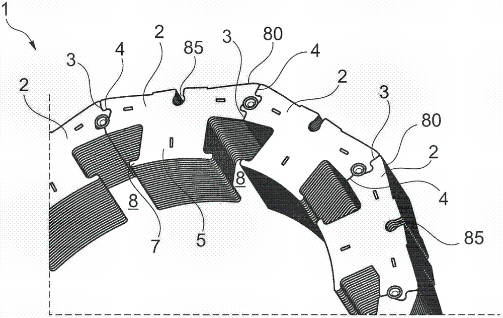
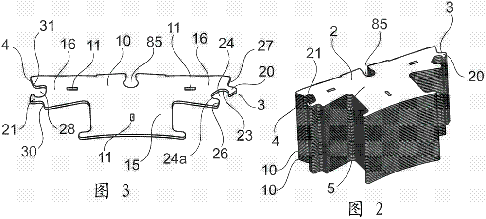
[0029] figure 1 The stator magnetic circuit 1 shown in , comprises a plurality of stacks 2 which are connected together at their flanks. Each stack 2 includes a tooth 5 of the magnetic circuit, which tooth is equipped with a pole shoe 7 in the example shown. As a variant, the tooth 5 does not have a pole piece. The magnetic circuit 1 defines between these teeth 5 notches 8 for receiving electrical conductors, not shown. Stators can have dense or distributed windings. As can be seen in FIG. 2 , each stack 2 is formed by stacking in sections identical magnetic plates 10 , one of these plates being represented in FIG. 3 . The panels 10 are connected together by mounting clips in the areas 11 in a conventional manner. Clamping areas 11 are located, for example, on the teeth 15 of each segment and on the annular yoke portion 16 intended to form a magnetic circuit behind the slot 8 .

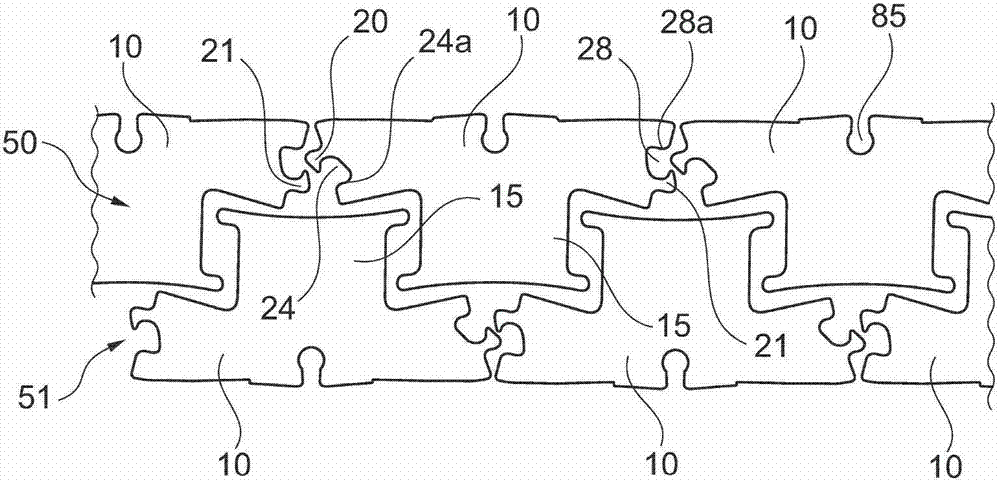
[0030] Ribs 20 and 21 are manufactured on the ends of these parts 16 , respectively on the fl...


PUM


Abstract

The invention relates to a magnetic circuit (1) for a rotary electric machine, comprising: stacks (2) of plates stacked in sections, the stacks being at their opposite flanks (3, 4) with socketed reliefs; and inserts introduced into openings defined at least in part by the sockets of these reliefs, which inserts ensure that the segments are connected in Together.

Description

technical field [0001] This invention relates to rotary electric machines, and more particularly to magnetic circuits for such machines. Background technique [0002] Excitation-induced magnetic circuits usually consist of stacks of plates. The sheets are often cut adjacently from a strip having a width substantially equal to the outer diameter of the inductor. It is also possible to cut these magnetic circuits into sections. Each segment then forms an angular fraction of a full revolution. The segments are then reassembled and stacked to form a complete magnetic circuit. [0003] In the first case, the difference between the consumed magnetic slab and the material actually required to conduct the magnetic flux is very large. It is not uncommon for the raw material used to represent twice as much material as is useful for flux passage. [0004] In the second case, the production in segments makes it possible to minimize the material consumed, since the smaller this angu...

Claims


Application Information

Patent Timeline
Patent Type & Authority Patents(China)
IPC IPC(8): H02K1/06H02K1/08H02K15/02
CPCH02K1/148H02K15/022Y10T29/49009H02K1/185
Inventor 帕特里克·沃尔格穆特
Owner MOTEURS LEROY SOMER
Why Eureka
Try Eureka