Vehicular brake control apparatus

a technology for controlling apparatus and brakes, applied in vehicle position/course/altitude control, braking system, instruments, etc., can solve the problems of reduced follow-up responsivity, insufficient absorbance of shock applied to passengers, and inability to obtain preferable acceleration.

Active Publication Date: 2016-07-19
SUBARU CORP
View PDF7 Cites 1 Cited by
  • Summary
  • Abstract
  • Description
  • Claims
  • Application Information

AI Technical Summary

Benefits of technology

[0012]Further, when it is required to use a relatively strong braking force to automatically stop the vehicle, in a typical brake pattern, a so called “temporal releasing” is performed by reducing the braking force for a short time before stopping the vehicle. This “temporal releasing” is performed in order to reduce the degree of lowering of the front of the vehicle (a nose-dive) when the vehicle is stopped and absorb a shock that a passenger receives due to a kickback when the main brakes are released. After that, the braking force is increased again to stop the vehicle. However, according to the technology disclosed in JP-A-2007-326399, since the auxiliary brakes are operated before the vehicle is automatically stopped, there is a disadvantage that the shock applied to the passenger cannot sufficiently be absorbed because of the braking operation of the auxiliary brakes even when the main brakes perform the “temporal releasing” operation.
[0016]In this point of view, the present invention has an object to provide a brake control apparatus for a vehicle capable of reducing a shock that a passenger receives and obtaining a riding comfort since a kickback generated to a vehicle body is small even when a braking operation of main brakes is released after auxiliary brakes are operated.
[0018]According to the present invention, when a braking operation by the auxiliary brakes is detected while the main brake controller is supplying a brake fluid pressure to the main brakes to stop the vehicle, the brake fluid pressure is rapidly reduced to a predetermined fluid pressure value and then the brake fluid pressure is gradually reduced to release the braking operation of the main brakes. With this configuration, even when the braking of the main brakes are released after the auxiliary brakes are operated, a kickback applied to the vehicle body is small and shock that the passenger receives can be reduced so that a riding comfort can be obtained.

Problems solved by technology

Therefore, for example, if the preceding vehicle starts to travel just before the vehicle automatically stops behind the preceding vehicle, since the auxiliary brakes is performing a braking operation even when the main brakes are released, there is a problem that the follow-up responsivity is reduced and preferable acceleration cannot be obtained.
However, according to the technology disclosed in JP-A-2007-326399, since the auxiliary brakes are operated before the vehicle is automatically stopped, there is a disadvantage that the shock applied to the passenger cannot sufficiently be absorbed because of the braking operation of the auxiliary brakes even when the main brakes perform the “temporal releasing” operation.
This generates a kickback applied to the vehicle body since the front wheels rotate and a shock is applied to the passenger.

Method used


Image

  • Vehicular brake control apparatus
  • Vehicular brake control apparatus
  • Vehicular brake control apparatus

Examples


Embodiment Construction

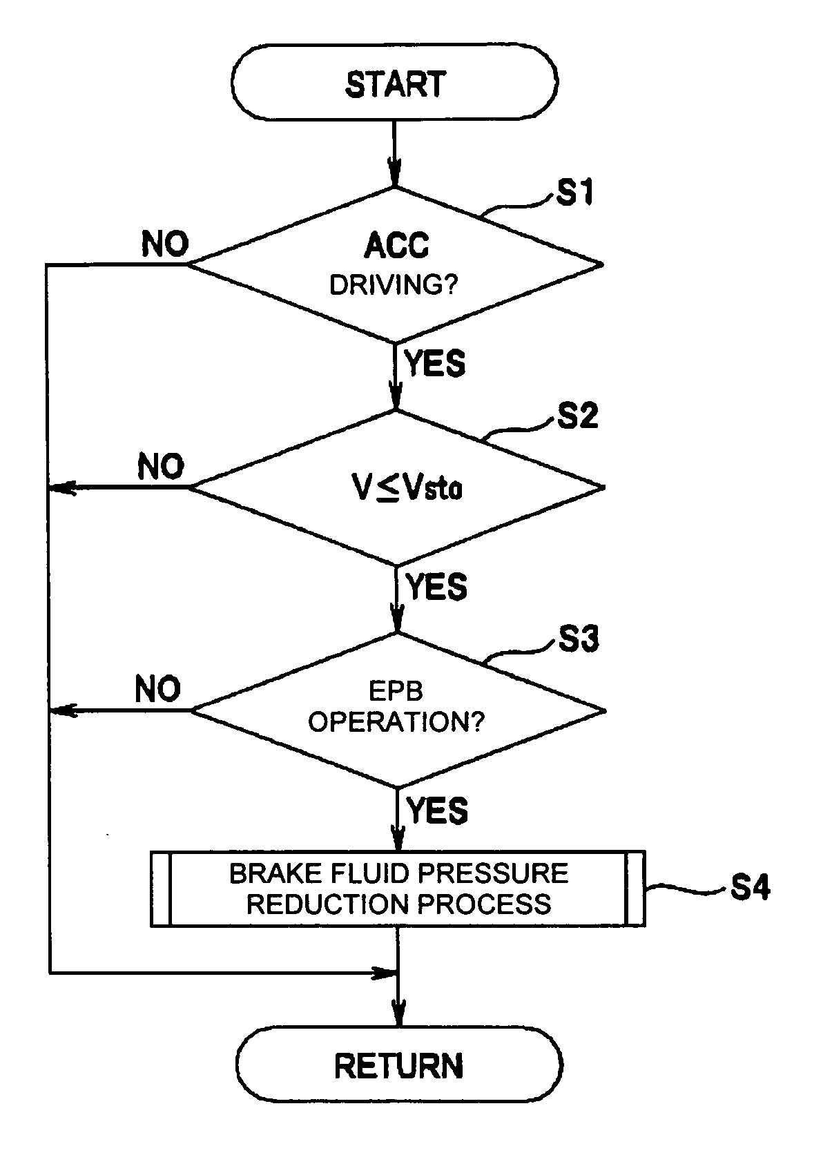
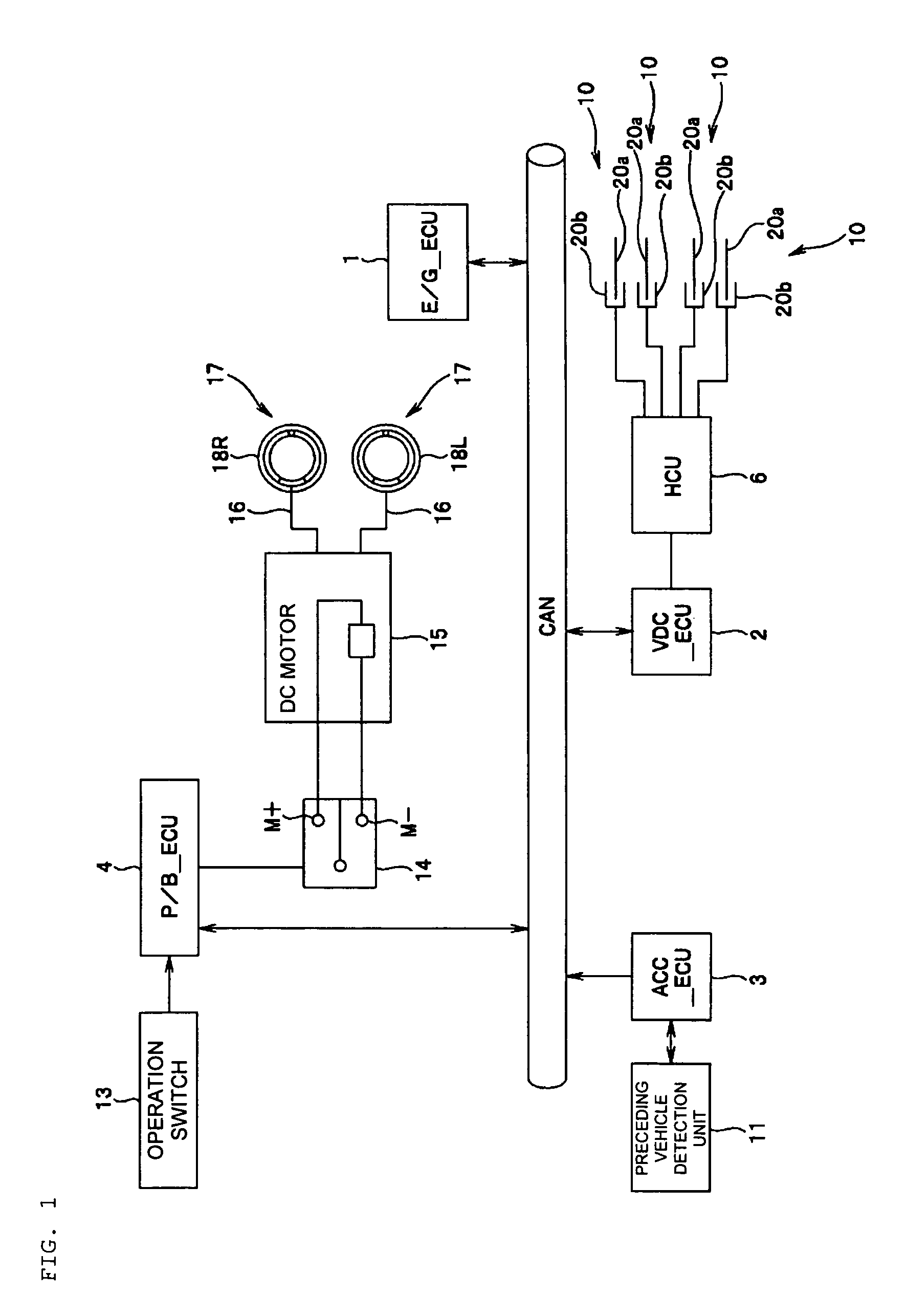
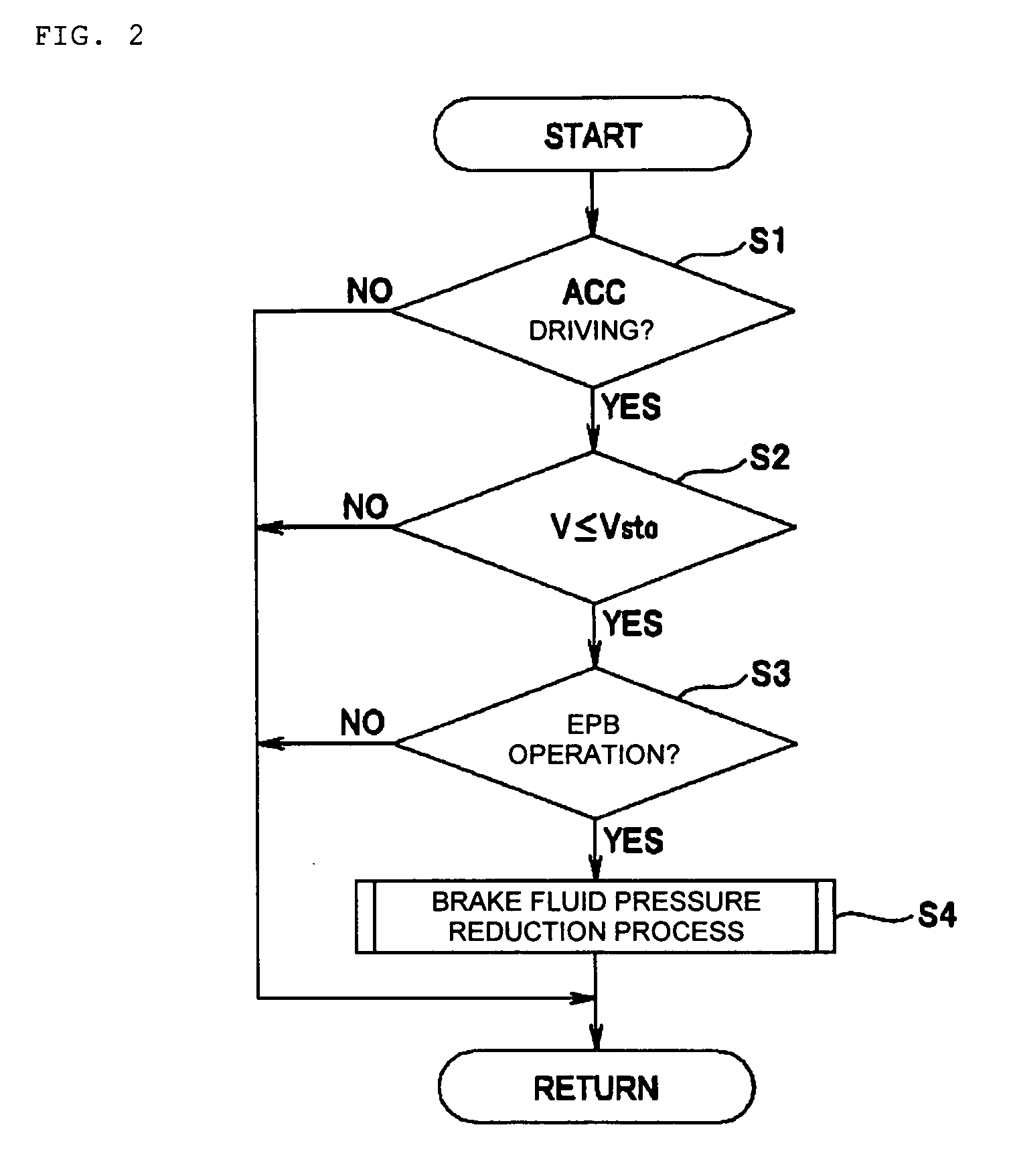
[0023]An embodiment of the present invention will be described with reference to the drawings. FIG. 1 shows a system configuration of a vehicle control apparatus.

[0024]A vehicle representing automobiles described in the present embodiment has various electrical control units which control driving conditions of the vehicle. FIG. 1 shows control units, among those various electrical control units, related to a vehicular brake control function described in the present embodiment, which are an engine control unit (E / G_ECU) 1, a vehicle dynamics control (VDC) unit (VDC_ECU) 2 serving as a main brake controller, an adaptive cruise control (ACC) unit (ACC_ECU) 3 and a parking brake control unit (P / B_ECU) 4 serving as an auxiliary brake controller. These ECUs 1 to 4 are mainly composed of microcomputers having a CPU, a ROM, a RAM, an input / output interface and the like, which are not shown, and the ECUs 1 to 4 are connected so as to communicate each other via a CAN (Controller Area Network)...


PUM


Abstract

A brake control apparatus includes a main brake controller configured to control a brake fluid pressure supplied to main brakes provided to a vehicle's four wheels according to a proceeding vehicle's traveling conditions to automatically stop the vehicle using a braking operation of the main brakes and maintain the stop condition and an auxiliary brake controller configured to control parking auxiliary brakes provided to right and left front wheels or right and left rear wheels of the vehicle to perform a braking operation so as to maintain the stop condition of the vehicle. When the auxiliary brakes perform the braking operation while the brake fluid pressure is being supplied to the main brakes to stop the vehicle, the main brake controller rapidly reduces the brake fluid pressure to a predetermined fluid pressure value and then gradually reduces the brake fluid pressure before the main brakes are released.

Description

CROSS-REFERENCE TO RELATED APPLICATIONS[0001]The disclosure of Japanese Patent Application No. 2008-298433 filed on Nov. 21, 2008 including the specification, drawings and abstract is incorporated herein by reference in its entirety.BACKGROUND OF THE INVENTION[0002]1. Field of the Invention[0003]The present invention relates to a brake control apparatus for a vehicle, capable of releasing a brake operation of main brakes when auxiliary brakes are operated after the main brakes perform the braking operation so as to stop the vehicle while the vehicle is in a follow-up driving state to follow a preceding vehicle.[0004]2. Description of Related Art[0005]A vehicle such as an automobile includes, as a brake apparatus, main brakes mainly operated during traveling and stopping and auxiliary brakes (parking auxiliary brakes) mainly operated during parking. The main brakes are configured to decelerate and stop the traveling vehicle by using brake fluid pressure as a braking force generated c...

Claims


Application Information

Patent Timeline
Patent Type & Authority Patents(United States)
IPC IPC(8): B60T13/66B60T7/22
CPCB60T7/22
Inventor MARUYAMA, TASUKU
Owner SUBARU CORP
Why Eureka
Try Eureka