Pill tray spatula

a technology of a spouting trough and a spouting trough, which is applied in the field of spouting troughs, can solve the problems of difficulty in quick and efficient opening of the trough by hand

Active Publication Date: 2016-07-19
DORETTI DAVID L
View PDF7 Cites 3 Cited by
  • Summary
  • Abstract
  • Description
  • Claims
  • Application Information

AI Technical Summary

Problems solved by technology

The openings of such containers are typically tightly sealed for security and safety reasons, and can be difficult to open by hand in a quick and efficient manner.

Method used


Image

  • Pill tray spatula
  • Pill tray spatula
  • Pill tray spatula

Examples


Embodiment Construction

[0027]The following detailed description is merely exemplary in nature and is not intended to limit the invention or the application and uses of the invention. Furthermore, there is no intention to be bound by any expressed or implied theory presented in the preceding technical field, background, brief summary or the following detailed description.

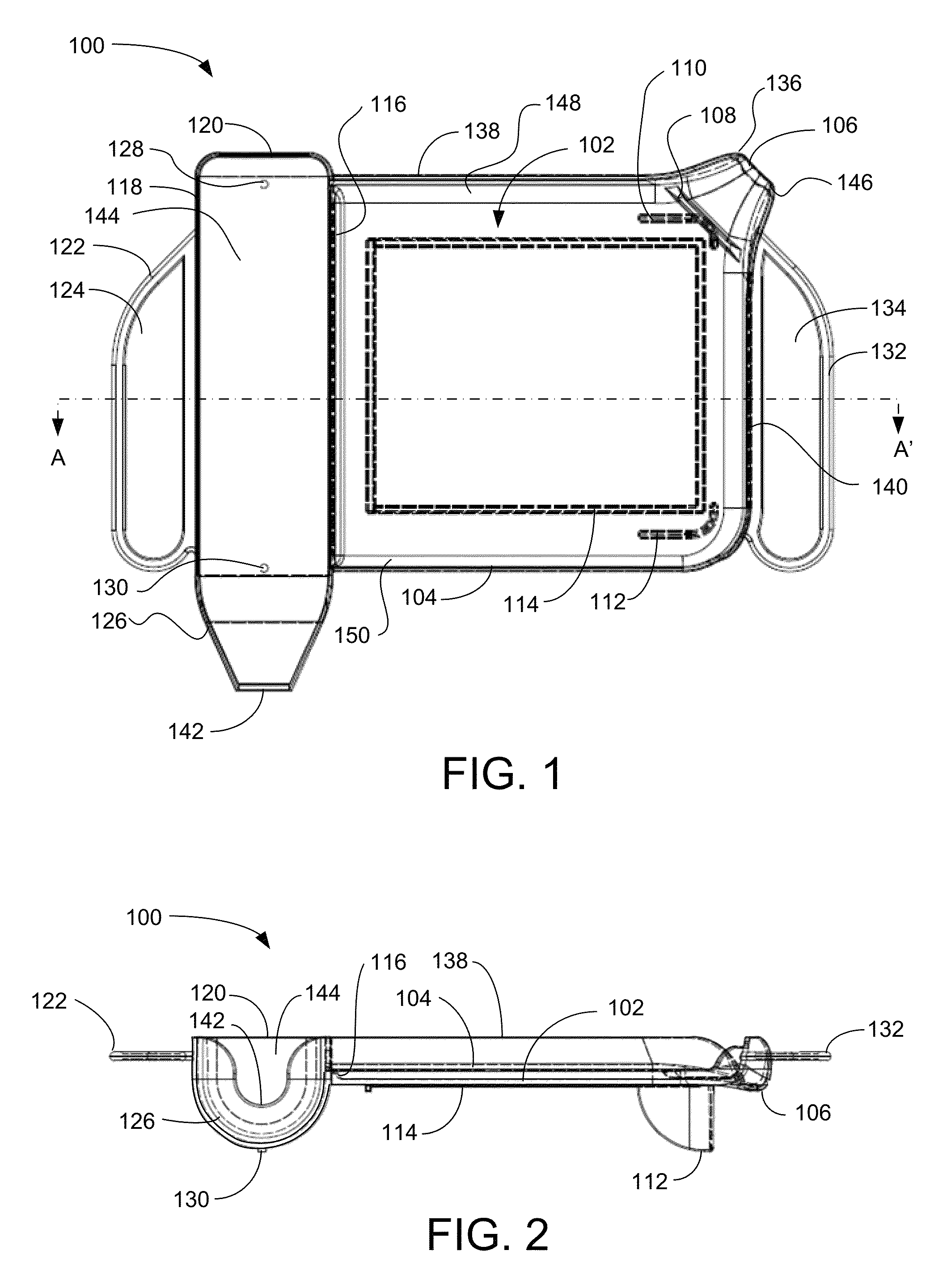
[0028]FIG. 1 is a top plan wire frame view illustrating an exemplary pill tray 100 and defining a cross-section AA′, according to a preferred embodiment of the present invention. The pill-supporting surface 102 of tray 100 arcuately merges with a rear wall 138, a front wall 104, and a side wall 140 with the directions referenced to FIG. 1 with rear at the top of the drawing. Pill receiver 144 lies along the left edge of the surface 102 and is separated from the surface 102 by a sloping ridge 116 that has no flat surfaces. Flat surfaces on the ridge 116 or between pill-supporting surface 102 and pill receiver 144 are preferably avoided to a...


PUM


Abstract

A pharmacist's spatula, or pill tray spatula, is provided for assisting in sorting and counting of pills and capsules comprising generally flat stainless steel blades extending from opposing ends of a generally bi-conic handle. The first blade has a straight portion less than or equal in length to a width or length of a pill counting tray, a curved portion between the straight portion and the handle and a curved and angled tip at the distal end of the first edge of the first blade. The second edge of the first blade has a notched hook, a fulcrum, and a bottle opener. The second blade is short and has the shape of a flat truncated arrow.

Description

RELATED APPLICATIONS[0001]This application is a continuation in part of U.S. patent application Ser. No. 13 / 468,445 filed May 10, 2012 to the same inventor.TECHNICAL FIELD[0002]The present invention generally relates to spatulas for pharmaceutical use, and more particularly relates to an apparatus for assisting in sorting pills and capsules, opening bottles and other pharmaceutical containers.BACKGROUND[0003]Pharmacist's spatulas, or pill tray spatulas, are used to count pills on pill trays. In the process of pill counting, pill containers must first be opened. The openings of such containers are typically tightly sealed for security and safety reasons, and can be difficult to open by hand in a quick and efficient manner.[0004]Accordingly, it is desirable to provide a single tool for both opening pill containers and for sorting and counting pills. Furthermore, other desirable features and characteristics of the present invention will become apparent from the subsequent detailed desc...

Claims


Application Information

Patent Timeline
Patent Type & Authority Patents(United States)
IPC IPC(8): B67B7/44B67B7/16B67B7/46A61J7/02
CPCB67B7/44A61J7/02B67B7/16B67B7/30A61J2205/30
Inventor CONNELLAN, JAMES A.MOYER, WILLIAM D.HAMBLIN, RYAN
Owner DORETTI DAVID L
Why Eureka
Try Eureka