
Optimization of unique antenna and RF systems for specific substrates

a technology of rf system and antenna, applied in the direction of program control, total factory control, instruments, etc., can solve the problems of unsightly antenna extending from a product, complex electromagnetic problems, complex design of rf circuit, etc., and achieve the effect of improving the design of the antenna

Active Publication Date: 2016-07-19
SCIPERIO
View PDF24 Cites 8 Cited by
  • Summary
  • Abstract
  • Description
  • Claims
  • Application Information

AI Technical Summary

Benefits of technology

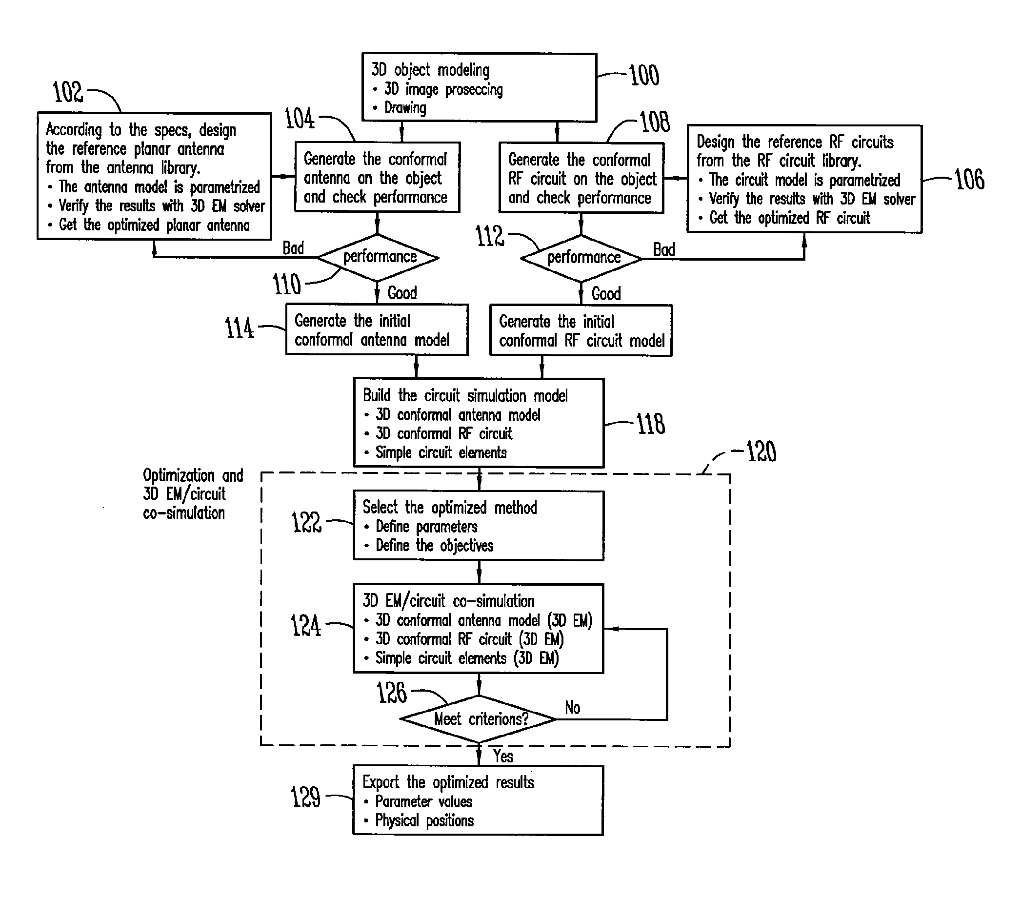
The present invention provides a method for incorporating an antenna into an object with a surface that acts as a substrate for the antenna. This method involves modeling the object as a three-dimensional object and designing the antenna to fit the surface of the object. The design can be improved using an evolutionary optimization process and the antenna can be placed on the surface of the object without a separate substrate. Additionally, the surface of the object can be modified by applying an underlayer before placing the antenna. This method allows for the efficient incorporation of antennas into objects with unique shapes and material properties.

Problems solved by technology

Although consumers perhaps have been conditioned not to notice, an antenna extending from a product can be unsightly.
A related problem is the complexity of design associated with antennas, RF circuits, high frequency circuits, and other types of complex AC circuit design.
Whereas DC circuit design is typically straightforward, the design of antennas, RF circuits, and other types of high frequency or complex AC circuit designs often present complex electromagnetic problems which must be solved to avoid adversely impacting the performance of the resulting design.

Method used


Image

  • Optimization of unique antenna and RF systems for specific substrates
  • Optimization of unique antenna and RF systems for specific substrates
  • Optimization of unique antenna and RF systems for specific substrates

Examples


Embodiment Construction

[0017]The present invention recognizes the need for the design of electronic circuits, particularly antennas and RF circuits, which are integrated into various products, devices, or other objects. The present invention provides for integrating antennas and circuits into an object in a manner which, instead of constraining the design of the object, including its shape and / or size, takes into account the three dimensional shape and / or size of the object in designing the antennas and circuits in a manner that does not sacrifice desired performance. Thus, the present invention provides for a process in which antennas and RF circuits are specifically designed based on the shape and size of the object such that they can be wrapped around the object or otherwise conformed to the object.

[0018]It is an object, feature, or advantage of the present invention in at least some of its embodiments to provide a methodology for designing antennas and RF systems that conform to various sizes and thre...


PUM


Abstract

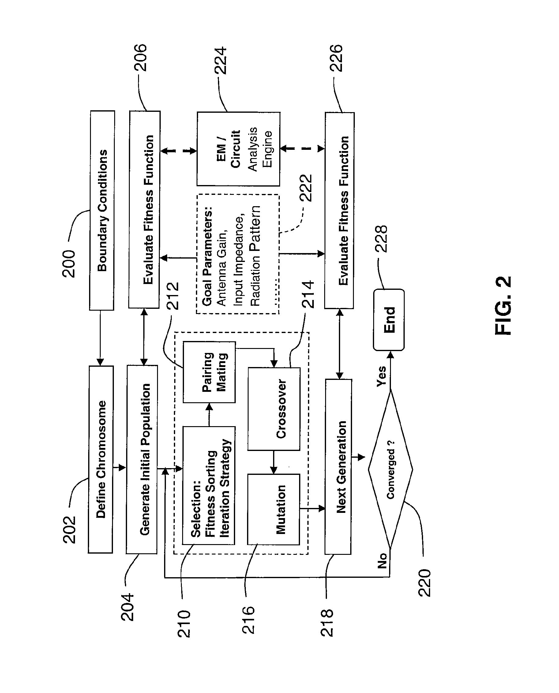
A method incorporating an antenna and RF circuitry into the object acting as a substrate includes modeling the object as a three-dimensional object, and designing the antenna and RF circuitry for direct placement on the surface of the object. The step of designing is at least partially based on the size, three-dimensional shape, and material properties of the surface of the object acting as the substrate. The step of designing is preferably performed through use of an evolutionary optimizer implemented using parallel computing devices.

Description

CROSS-REFERENCE TO RELATED APPLICATIONS[0001]This application claims the benefit of provisional patent application Ser. No. 60 / 595,073, filed Jun. 3, 2005, entitled Parallel Optimization for Antenna Systems, the contents of which are hereby incorporated by reference in their entirety.FIELD OF THE INVENTION[0002]The present invention relates generally to the design of electronic circuits, including, without limitation, antennas and RF circuits for integration into products, devices or other objects.BACKGROUND OF THE INVENTION[0003]Product designs are often constrained by the need to include antennas and radio frequency (RF) circuits. Whether it is an antenna extending from a car or from a cell phone, antennas are incorporated into various product designs. Although consumers perhaps have been conditioned not to notice, an antenna extending from a product can be unsightly. Product designs can be particularly constrained by antenna design in products or devices having small size or irre...

Claims


Application Information

Patent Timeline
Patent Type & Authority Patents(United States)
IPC IPC(8): G06F17/50G05B19/4097
CPCG05B19/4097G05B2219/34198Y02P90/02
Inventor CHURCH, KENNETH H.TAYLOR, ROBERT M.WILHELM, MICHAEL J.DONG, HAOLI, YANZHONG
Owner SCIPERIO
Learn More