
Resistor and method of manufacture

a resistor and metal strip technology, applied in the direction of resistor details, resistors adapted for terminal application, resistive material coating, etc., can solve the problems of low material utilization, complex manufacturing process, and traditional techniques for manufacturing surface mount metal strip resistors with relatively precise ohmic values that suffer from typical problems such as low material utilization, to achieve uniform thickness

Active Publication Date: 2016-07-19
VISHAY DALE ELECTRONICS INC
View PDF15 Cites 21 Cited by
  • Summary
  • Abstract
  • Description
  • Claims
  • Application Information

AI Technical Summary

Benefits of technology

The present technology relates to a method of manufacturing resistors and a resistor structure. The method includes coating the resistive material with insulative layers and then removing certain parts of the insulative layers to create conductive pads. These pads have resistance values that are measured, and based on the measurements, additional ins European patent text describes a method of manufacturing resistors and the structure they are made of. The method involves coating the resistive material with layers of insulation, and then removing parts of the insulation based on the measured resistance between different parts. This process helps to create conductive pads with precise resistance values. The resulting resistors have a long lifespan and can be used in various electronic devices. The resistor structure includes resistive material, insulation layers, and conductive pads that work together to regulate the flow of electric current.

Problems solved by technology

Conventional techniques for manufacturing surface mount metal strip resistors with relatively precise ohmic values typically suffer from low material utilization, complex manufacturing processes, and the like.

Method used


Image

  • Resistor and method of manufacture
  • Resistor and method of manufacture
  • Resistor and method of manufacture

Examples


Embodiment Construction

[0012]Reference will now be made in detail to the embodiments of the present technology, examples of which are illustrated in the accompanying drawings. While the present technology will be described in conjunction with these embodiments, it will be understood that they are not intended to limit the invention to these embodiments. On the contrary, the invention is intended to cover alternatives, modifications and equivalents, which may be included within the scope of the invention as defined by the appended claims. Furthermore, in the following detailed description of the present technology, numerous specific details are set forth in order to provide a thorough understanding of the present technology. However, it is understood that the present technology may be practiced without these specific details. In other instances, well-known methods, procedures, components, and circuits have not been described in detail as not to unnecessarily obscure aspects of the present technology.

[0013]...


PUM


Abstract

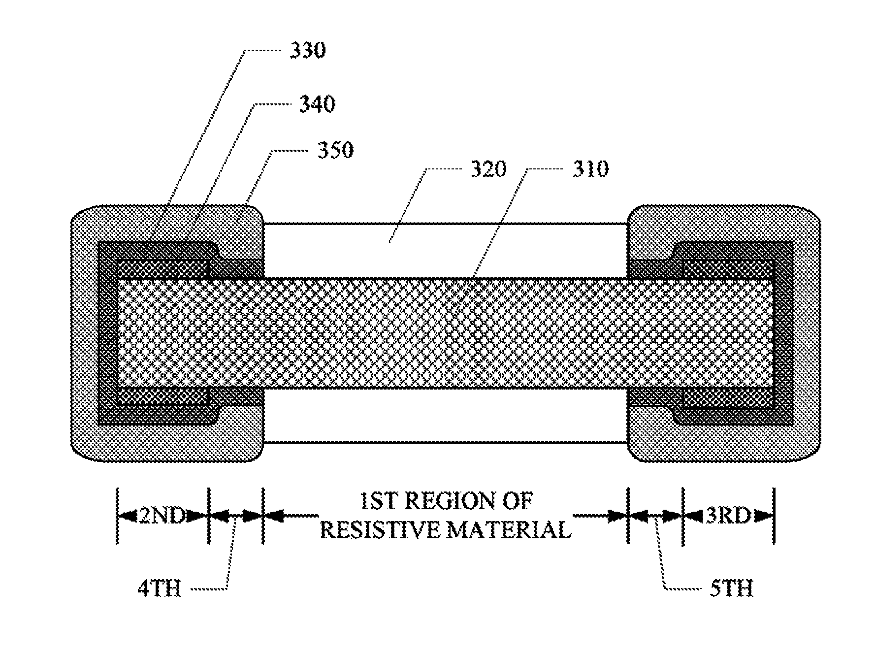
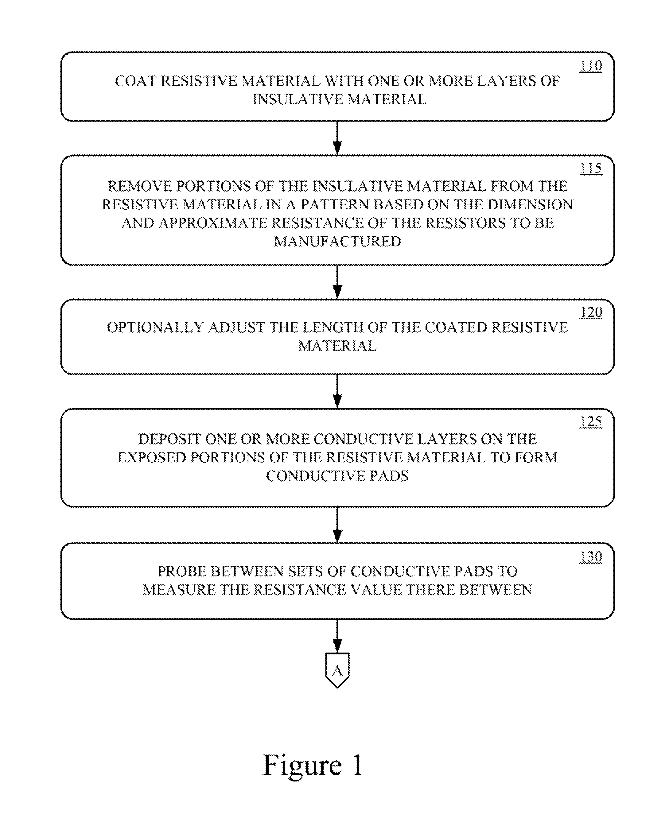
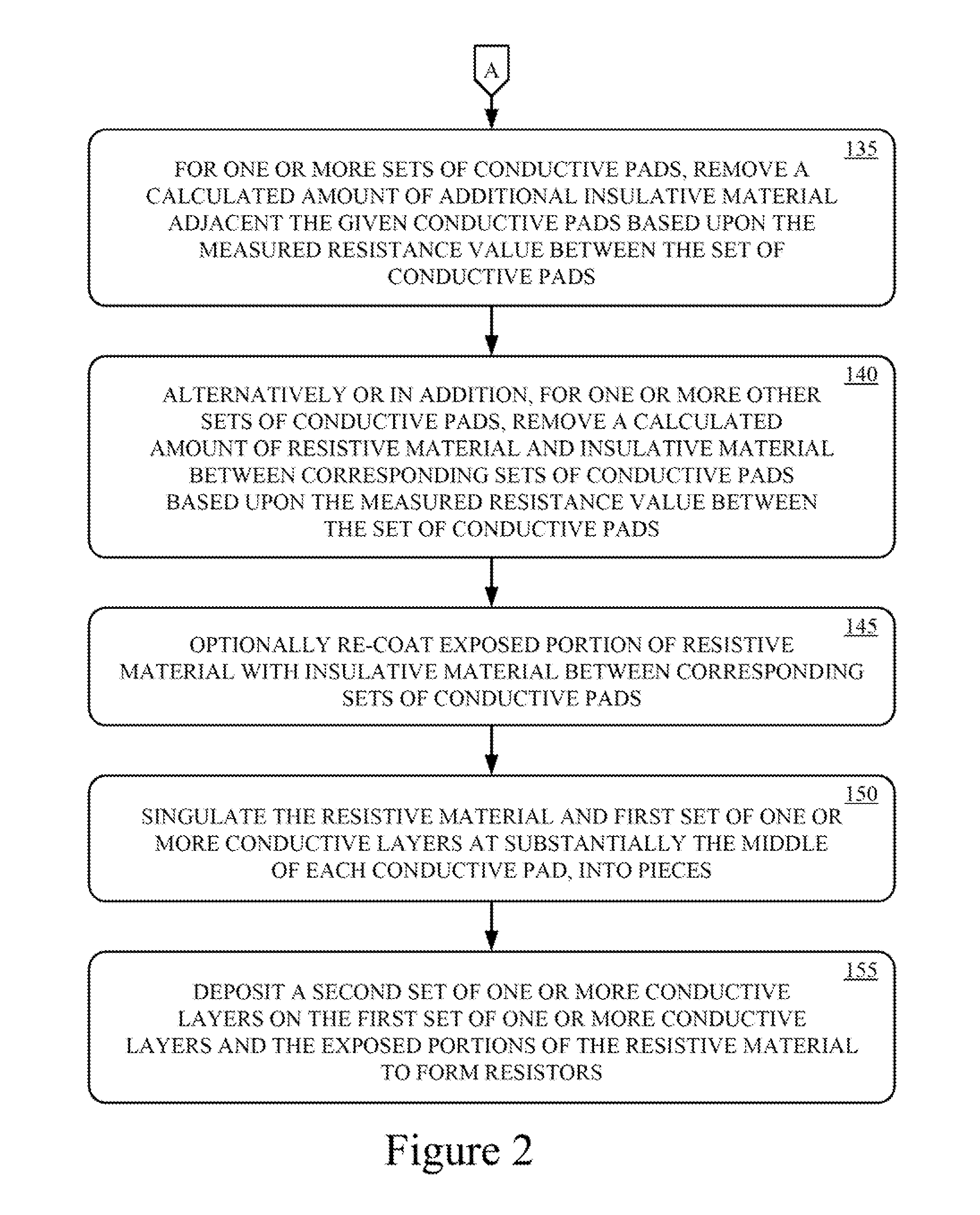
The present technology is directed toward a resistor and method of manufacturing the resistor. One or more layers of insulative material are formed on a length of resistive material. Portions of the one or more layers insulative material are removed from the resistive material in a pattern based on a predetermined approximate dimension and predetermined approximate resistance value. A first set of one or more conductive layers are formed on the portions of the resistive material exposed by the insulative coating to form a plurality of conductive pads on the resistive material between the patterned insulative material. The sets of conductive pads are probed to measure a preliminary resistance value between the sets of conductive pads. For one or more sets of conductive pads, a calculated amount of additional insulative material adjacent the respective conductive pads is removed based upon the preliminary resistance value between the corresponding set of conductive pads and a final resistance value to exposed additional portions of resistive material. The conductive pads and resistive material is cut at substantially the middle of each conductive pad to form pieces. A second set of one or more conductive layers are formed on the first set of one or more conductive layers at opposing ends of each piece, and the additionally exposed portions of the resistive material.

Description

BACKGROUND OF THE INVENTION[0001]Surface mount resistors are widely utilized in electronic devices. One common type of surface mount resistor is the metal strip resistor. A surface mount metal strip resistor may have a value that ranges between 100 micro-Ohms (μΩ) and 10 Ohms (Ω). One exemplary, but non-limiting, use of low ohmic value surface mount metal strips resistors is in current sensing applications. In such applications, the ohmic value of the resistor needs exhibit a relatively precise value.[0002]Conventional techniques for manufacturing surface mount metal strip resistors with relatively precise ohmic values typically suffer from low material utilization, complex manufacturing processes, and the like. Therefore, there is a continuing need for improved manufacturing techniques for surface mount metal strip resistors exhibiting a relatively tight tolerance in their ohmic value.SUMMARY OF THE INVENTION[0003]The present technology may best be understood by referring to the fo...

Claims


Application Information

Patent Timeline
Patent Type & Authority Patents(United States)
IPC IPC(8): H01C1/142H01C17/06H01C7/00
CPCH01C17/06H01C7/00H01C1/148H01C7/001H01C17/02H01C17/24H01C17/281H01C1/142H01C17/28
Inventor WYATT, TODDSMITH, CLARKBRUNE, RODKLABUNDE, ROCKY
Owner VISHAY DALE ELECTRONICS INC
Learn More