Electroacoustic transducer

a transducer and electroacoustic technology, applied in the direction of piezoelectric/electrostrictive transducers, diaphragm construction, transducer diaphragms, etc., to achieve the effect of wide directivity, wide directivity, and high sound pressur

Active Publication Date: 2016-07-19
YAMAHA CORP
View PDF16 Cites 3 Cited by
  • Summary
  • Abstract
  • Description
  • Claims
  • Application Information

AI Technical Summary

Benefits of technology

[0014]In the case where the electroacoustic transducer according to the present invention is applied to a speaker, this speaker provides a higher sound pressure at low frequencies due to piston motion and has wide directivity at middle and low frequencies due to radiation of reproduced sound from the respective convex surfaces of the pair of longitudinal split tubular members. As a result, a full-range speaker unit having wide directivity over a wide range extending from low frequencies to middle and high frequencies can be achieved by a single speaker unit with low cost. Also in the case where the electroacoustic transducer according to the present invention is applied to a microphone, this microphone can pick up sound with wide directivity over a frequency range extending from low frequencies to high frequencies.

Problems solved by technology

However, since the riffell speaker of this type is not appropriate for reproducing sound at low frequencies, a multi-speaker system using a speaker for low frequencies (i.e., a woofer) needs to be additionally configured to reproduce sound over the full range of audible frequencies.

Method used


Image

  • Electroacoustic transducer
  • Electroacoustic transducer
  • Electroacoustic transducer

Examples


first embodiment

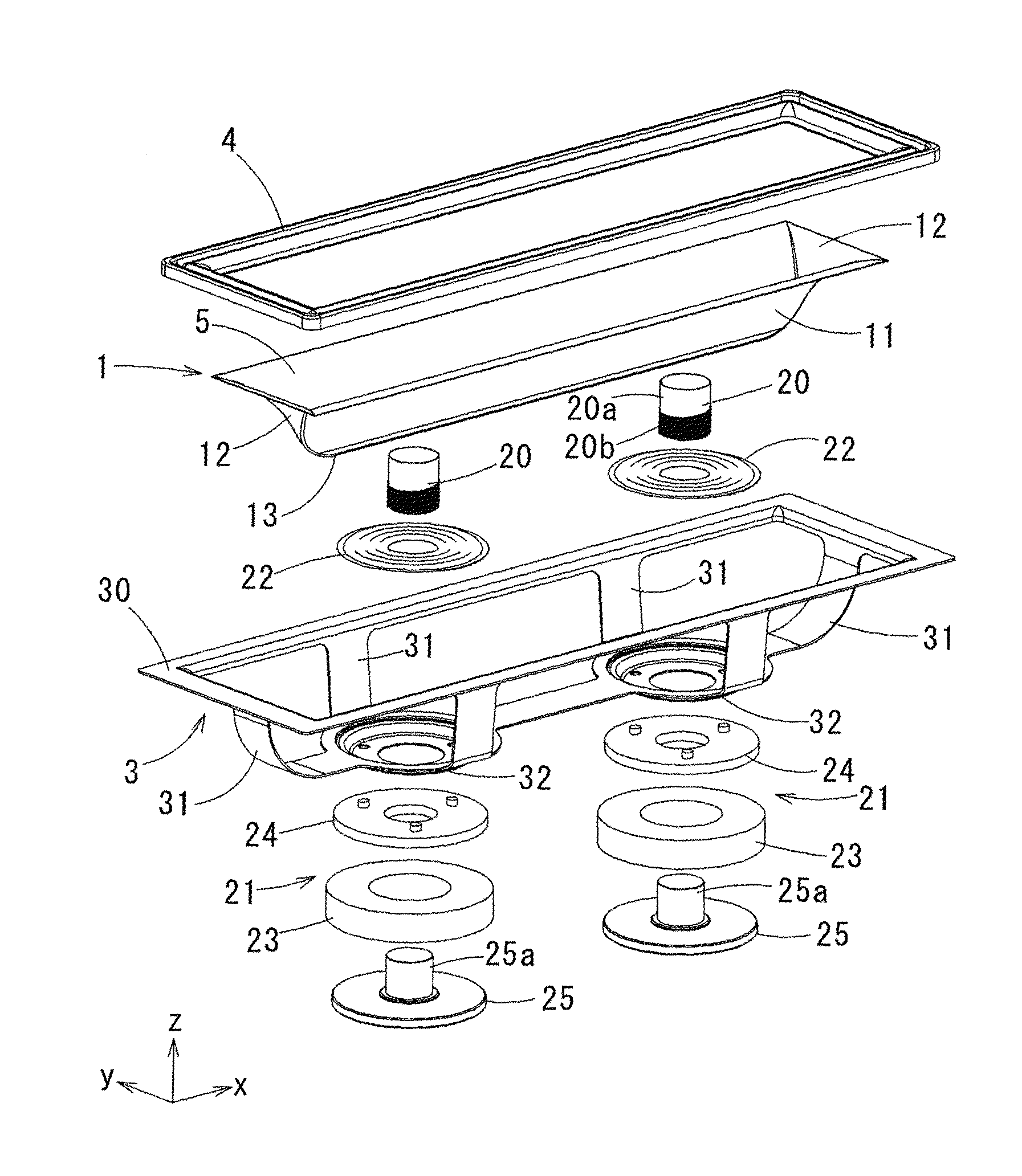
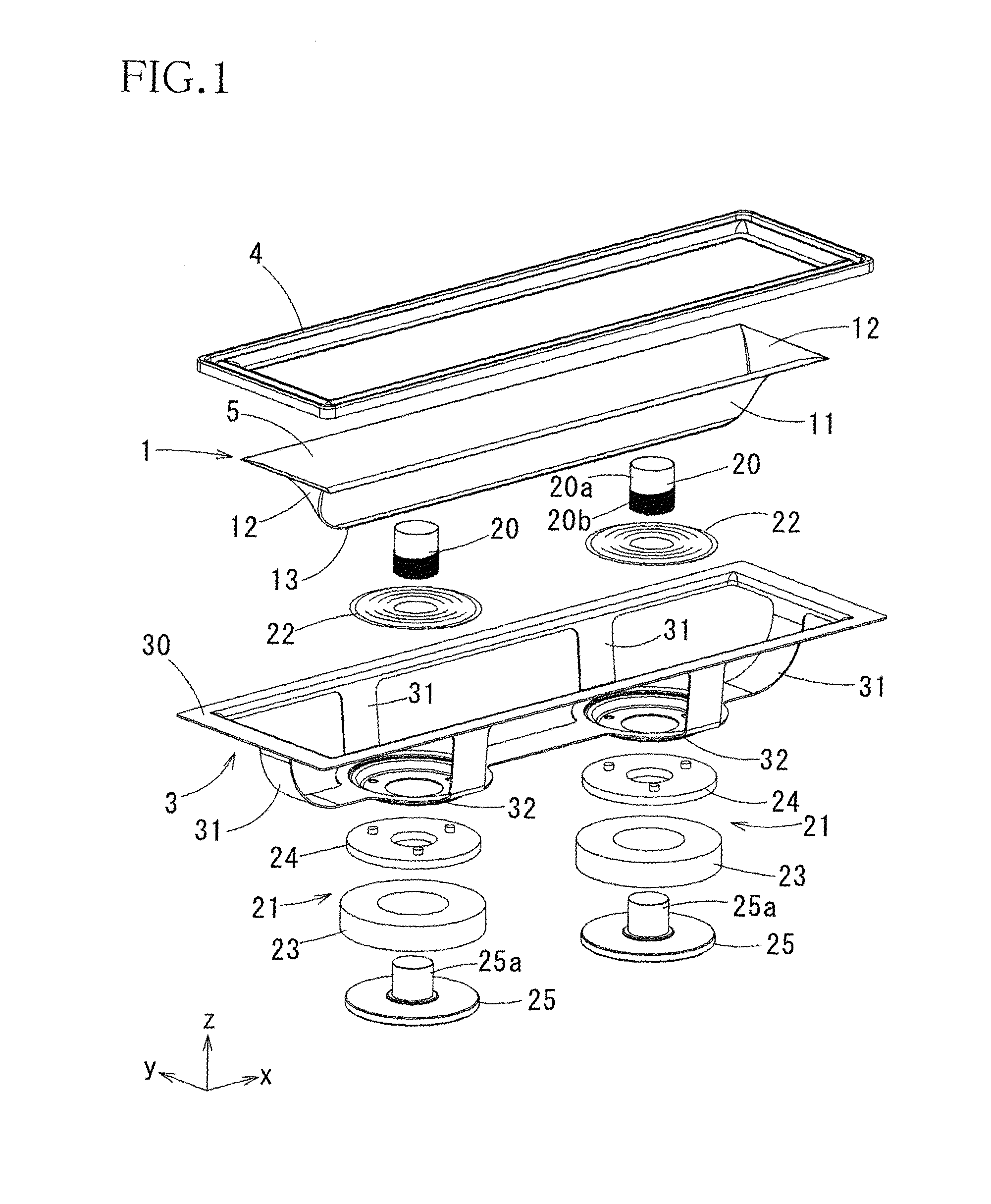
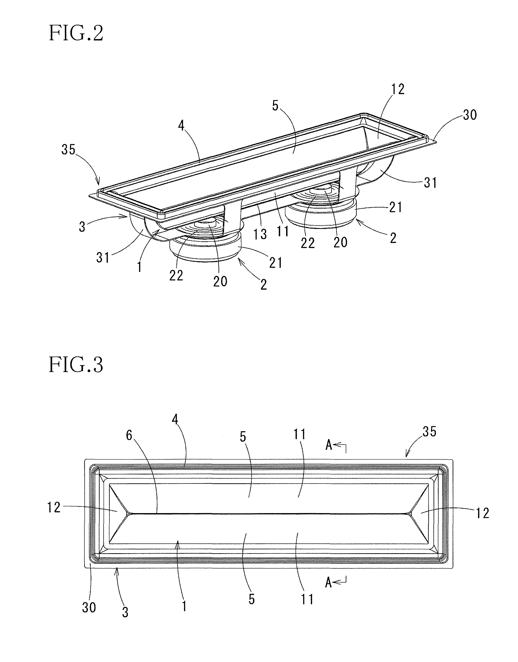
[0037]FIGS. 1-5 illustrate a speaker according to the present invention.

[0038]The speaker according to the present embodiment (as one example of an electroacoustic transducer) includes: a diaphragm 1; actuators 2 (as one example of a converter) for causing reciprocation of the diaphragm 1; a support frame 3 for supporting the diaphragm 1 and the actuators 2; and an edge member 4 for supporting the diaphragm 1 such that the diaphragm 1 is reciprocable relative to the support frame 3.

[0039]In the state illustrated in FIG. 1, the up and down direction is defined such that the upper side is a side on which the edge member 4 is provided in FIG. 1, and the lower side is a side on which the actuators 2 are provided in FIG. 1. Also, the lengthwise direction of the support frame 3 having a rectangular shape as will be described below is defined as the front and rear direction, and the widthwise direction of the support frame 3 as the right and left direction. Also, a surface of the support f...


PUM


Abstract

An electroacoustic transducer includes a diaphragm including a pair of convex surfaces respectively including convex surfaces of a pair of longitudinal split tubular members. A valley is formed between one side portions of the pair of longitudinal split tubular members. The electroacoustic transducer further includes: a converter configured to convert between a vibration of the diaphragm in a depth direction of the valley and an electric signal corresponding to the vibration; and a supporter supporting other side portions of the pair of longitudinal split tubular members of the diaphragm so as to allow the other side portions to vibrate in a vibration direction of the vibration.

Description

CROSS REFERENCE TO RELATED APPLICATION[0001]The present application claims priority from Japanese Patent Application Nos. 2013-219606 filed on Oct. 22, 2013, 2013-239320 filed on Nov. 19, 2013, and 2014-200338 filed on Sep. 30, 2014, the disclosures of which are herein incorporated by reference in its entirety.BACKGROUND[0002]1. Technical Field[0003]The present invention relates to an electroacoustic transducer for a speaker configured to reproduce sound by vibrating convex surfaces and a microphone configured to pick up sound.[0004]2. Description of the Related Art[0005]A typical dynamic speaker includes a vibration plate or a diaphragm and a voice coil motor which moves the vibration plate back and forth to cause piston motion for producing sound. The typical dynamic speaker functions substantially as a point sound source and exhibits wide directivity at low frequencies but exhibits sharp directivity over a frequency range equal to or higher than a frequency at which the diameter ...

Claims


Application Information

Patent Timeline
Patent Type & Authority Patents(United States)
IPC IPC(8): H04R1/00H04R7/18H04R9/06H04R7/12H04R7/20H04R9/00H04R17/00H04R31/00H04R7/14
CPCH04R7/20H04R7/12H04R7/18H04R9/06H04R7/14H04R9/00H04R9/063H04R17/00H04R31/00H04R2207/021H04R2231/003
Inventor NORO, MASAOARAI, AKIRA
Owner YAMAHA CORP
Why Eureka
Try Eureka