
Fuel level sensor

a technology of level sensor and fuel, which is applied in the direction of liquid/fluent solid measurement, machines/engines, instruments, etc., can solve the problems of fuel sloshing and mechanical breakdown, mechanical sensor types suffer from a variety of inadequacies, and achieve the effect of dissipating heat more readily

Inactive Publication Date: 2016-07-26
SCHOENBERG GREGORY B
View PDF8 Cites 38 Cited by
  • Summary
  • Abstract
  • Description
  • Claims
  • Application Information

AI Technical Summary

Benefits of technology

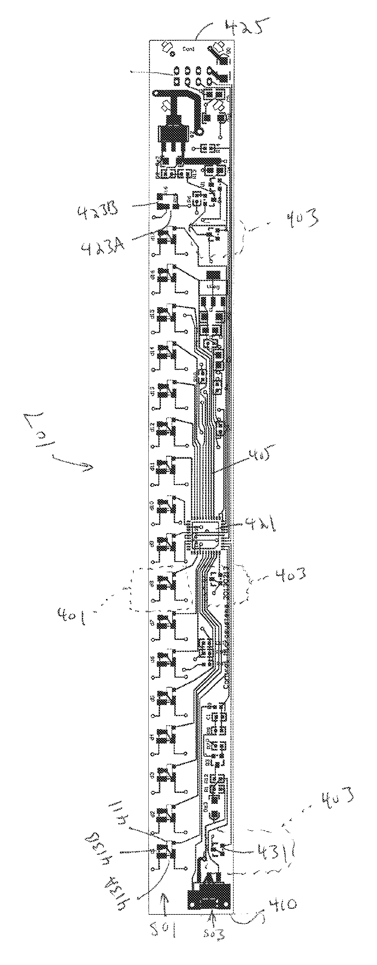
The patent describes an electronic fuel sensor that uses the characteristics of fluid (such as gasoline) to dissipate heat more readily than air. The sensor consists of a vertical array of sensors, including measurement sensors and calibration sensors. The measurement sensors have a thermal diode and a resistor, while the calibration sensors have a thermal diode and a resistor. The sensors record the change in temperature caused by the heat generated by the resistor and use this information to calculate the level of fluid into which the sensor is immersed. The sensor can be attached to a fuel tank mounting and is coated with a polymer called poly(p-xylylene) polymer. The technical effect of this invention is to provide a more accurate and reliable fuel level sensor for automobiles.

Problems solved by technology

These types of mechanical sensors suffer from a variety of inadequacies, including sensitivity to fuel types, fuel sloshing and mechanical breakdowns.
Fuel sloshing is a particular problem in determining the amount of fuel in a fuel tank.
While the level will generally be fairly static when the vehicle is idling at rest, vibration of the automobile combined with its movement, change in the elevation of terrain being traversed, and other factors can all serve to make the measurement of the amount of fuel in the fuel tank more difficult than expected.
To deal with this problem, many mechanical systems are designed to be purposefully slow to react such as by having delay built in.
Further, mechanical fuel sensors can have problems with the variety of fuel types on the market today.
The introduction of ethanol and other fuel additives to gasoline, which are often added in not insubstantial percentages, can cause mechanical fuel gauges to read consistently wrong.
Since a mechanical fuel gauge generally floats on the surface of the fuel, substantial changes in fuel density and other properties can result in a fixed level of error being introduced to the sensor.
Further, ethanol, and a number of other fuel additives, are highly corrosive and can cause damage to the mechanical or electrical components of the fuel sensor.
This requires stocking an increased number of parts and presents the potential problem that a vehicle is assembled with an inaccurate fuel sensor and will always read inaccurately or with a fuel sensor that is simply inadequate for the vehicle.
This can result in an unexpected breakdown for the owner when they unexpectedly run out of fuel and can also result in difficulty when repairs are required.

Method used


Image

  • Fuel level sensor
  • Fuel level sensor
  • Fuel level sensor

Examples


Embodiment Construction

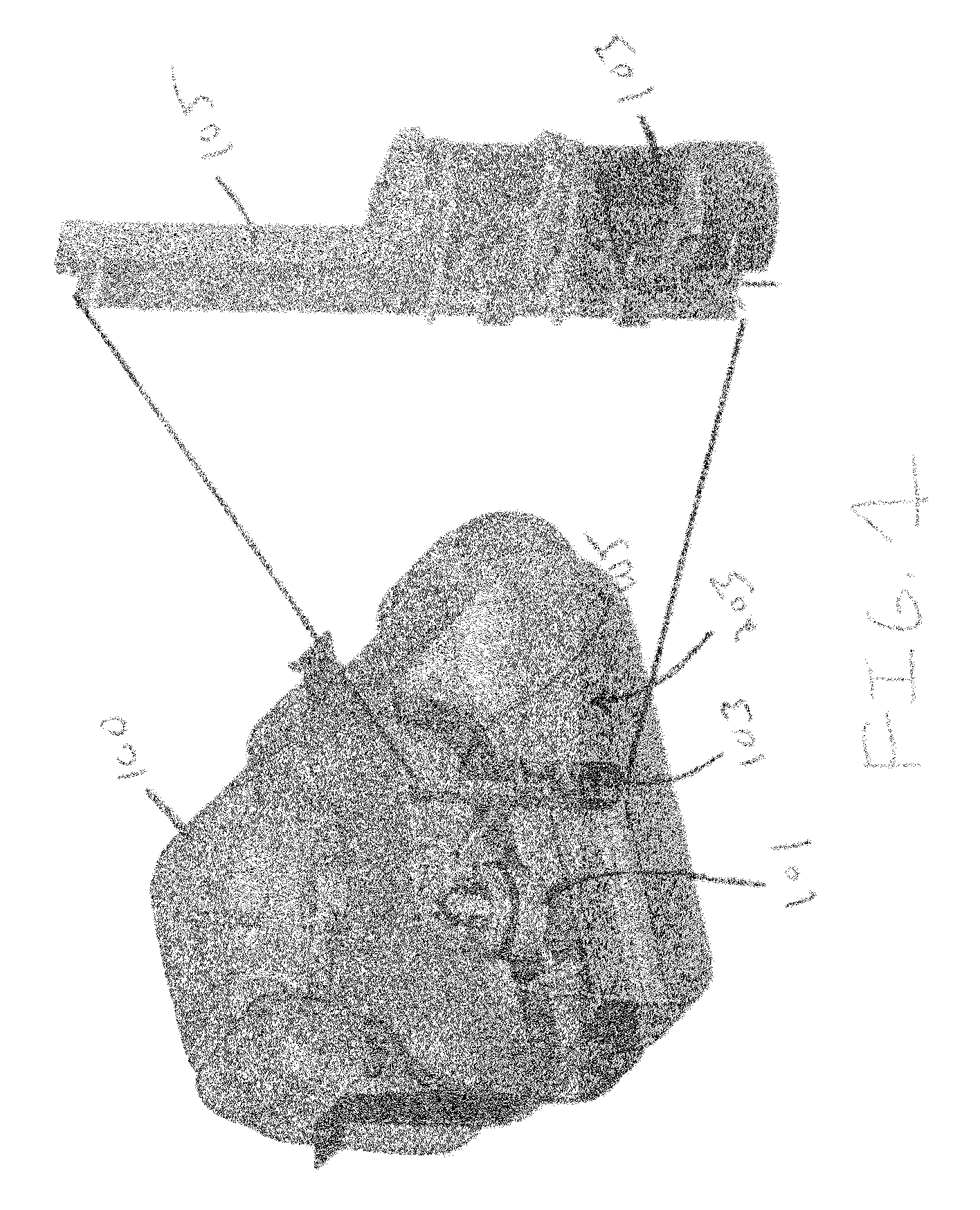
[0034]FIG. 1 provides for a cutaway view of a typical fuel tank (100) of an automobile. All fuel tanks in modern automobiles are of unique shape as they are generally fit into the vehicle after all the other components are placed and are simply allowed to fill available space. Thus, as can be seen in FIG. 1, the tank (100) often has a very convoluted shape which is not regular. Generally toward the fluid center of the tank is a FDM (101) which serves to feed fuel from the tank (100) to the engine. The fuel delivery module (FDM) (101) is generally situated in a location so that it is somewhat insulated from fuel sloshing or flowing around in the tank (100) to insure that the flow of fuel to the engine is constant.

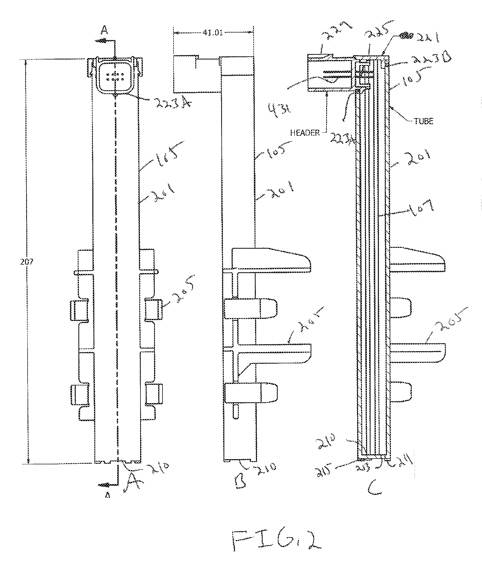
[0035]There is also attached in the tank a fuel level sensor. The sensor is in a housing (105). The housing (105) is attached to a connector (103) for the purposes of mounting it in the tank (100). The housing (105) will generally be positioned towards the fluid center of th...


PUM


Abstract

An electronic fuel sensor which utilizes the characteristics of fluid (such as gasoline) to dissipate heat more readily than a gas. Specifically the fuel sensor utilizes a linear array of sensors comprising a couple heat detector and heat source which can determine which of the sensors are in fluid and which are in air.

Description

BACKGROUND[0001]1. Field of the Invention[0002]The invention generally relates to fluid level sensors; in particular, to a solid state fuel level sensor for automobiles.[0003]2. Description of Related Art[0004]When driving an automobile, it is important that the driver know how much fuel remains within the gas tank so that he or she can refuel the vehicle before it runs out of fuel. While automobiles have become increasingly sophisticated over the years, vehicle fuel sensors have mostly stayed the same. Traditional sensors utilize a mechanical action associated with a float valve or level disposed within the fuel tank. The float valve or level will generally alter the resistance of a variable resistor based on the height of the fuel in the tank as the float valve floats on the fuel's surface. This resistance can then be communicated via standard onboard electronics to an automobile's onboard processor which can provide an indication of the fuel level to the driver. The value can be ...

Claims


Application Information

Patent Timeline
Patent Type & Authority Patents(United States)
IPC IPC(8): G01F19/00G01F23/00G01F25/00G01F23/24
CPCG01F25/0061G01F23/246G01F23/248G01F25/20
Inventor SCHOENBERG, GREGORY B.
Owner SCHOENBERG GREGORY B
Learn More