
Sheet bundle binding processing apparatus and image forming system having the same

a technology of image forming system and binding processing apparatus, which is applied in the direction of electrographic process, instruments, transportation and packaging, etc., can solve the problems of weakened or released bonding, image blurring, and sheet folding or skewed sheets, so as to prevent the effect of getting dirty and simple structur

Active Publication Date: 2016-08-09
COPYER +1
View PDF6 Cites 15 Cited by
  • Summary
  • Abstract
  • Description
  • Claims
  • Application Information

AI Technical Summary

Benefits of technology

[0014]An object of the present invention is to provide a sheet bundle binding processing apparatus capable of providing relatively strong bonding when a plurality of sheets are bound with nip-pressure deformation and causing less frictional damage on a sheet face when a sheet bundle is introduced to and discharged from the binding unit.
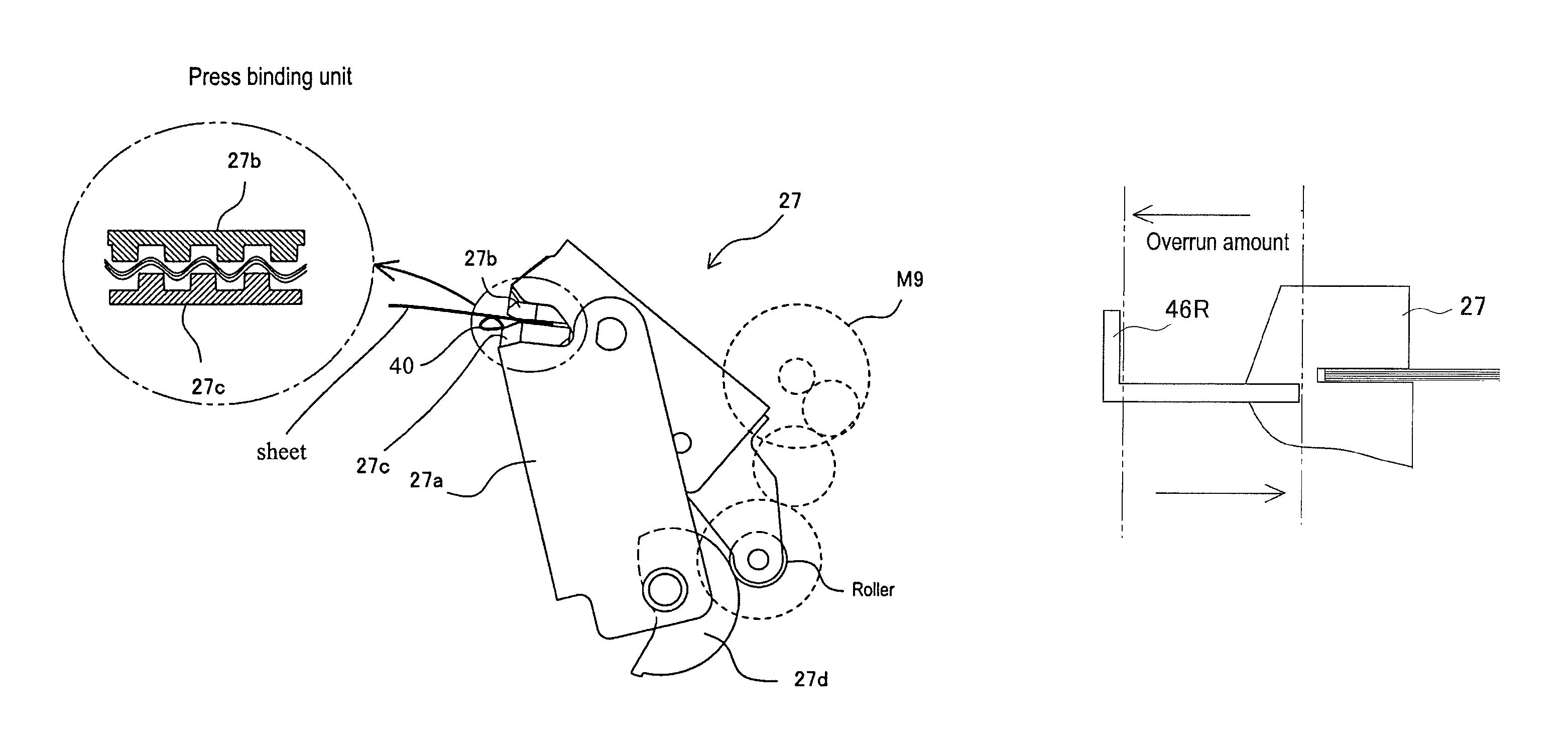
[0017]In the present invention, a binding process is performed on a plurality of sheets by pressure-nipping the sheets with the corrugation-shaped pressurizing faces and forming linear scars thereon, and then, the bound sheet bundle is offset by a predetermined amount in a direction intersecting with the bundle discharging direction and discharged in the bundle discharging direction. According to the above, following effects are obtained.
[0018]The taking-off device applies a force (feeding force), in a direction of taking-off from the corrugation-shaped pressurizing faces, to an end face of a sheet bundle which is mutually intimately-contacted with pressure-nipping by the pressurizing faces. Accordingly, the bound sheet bundle is prevented from being separated or getting incomplete even with discharging action of the bound sheet bundle from the binding position.
[0019]Along with the above, since the bound sheet bundle is discharged in the bundle discharging direction after being offset from the binding position by a predetermined amount in the direction intersecting with the bundle discharging direction, a face of the sheet bundle to be discharged is prevented from rubbing against the pressurizing faces at the binding position during being discharged. Accordingly, the sheet face is prevented from getting dirty and damaged.
[0020]Further, in the present invention, the taking-off device is structured with the side regulating plate which biases and regulates sheets on the processing tray. Accordingly, a sheet bundle can be taken off from the binding position in a state of maintaining the bonded state and jumping of the sheet bundle due to the taking-off can be prevented with a simple structure without requiring a special mechanism.

Problems solved by technology

With such a structure, a conventional non-staple binding unit causes following problems.
There is a fear that an end face of sheets is stuck to a corrugation part of the pressurizing face and the sheets are folded or skewed when the sheets are conveyed to a binding position.
In addition, since the sheet bundle is discharged as being slid on the corrugation part of the binding device, there arises a problem of image blurring.
In this case, there may be a case that bonding is weakened or released when the sheet bundle is forcedly discharged.

Method used


Image

  • Sheet bundle binding processing apparatus and image forming system having the same
  • Sheet bundle binding processing apparatus and image forming system having the same
  • Sheet bundle binding processing apparatus and image forming system having the same

Examples


Embodiment Construction

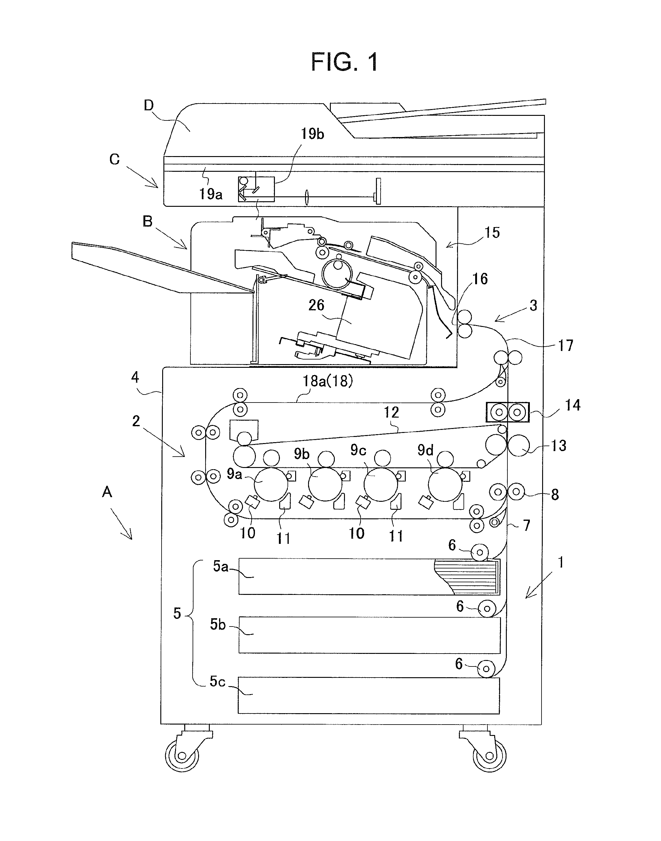
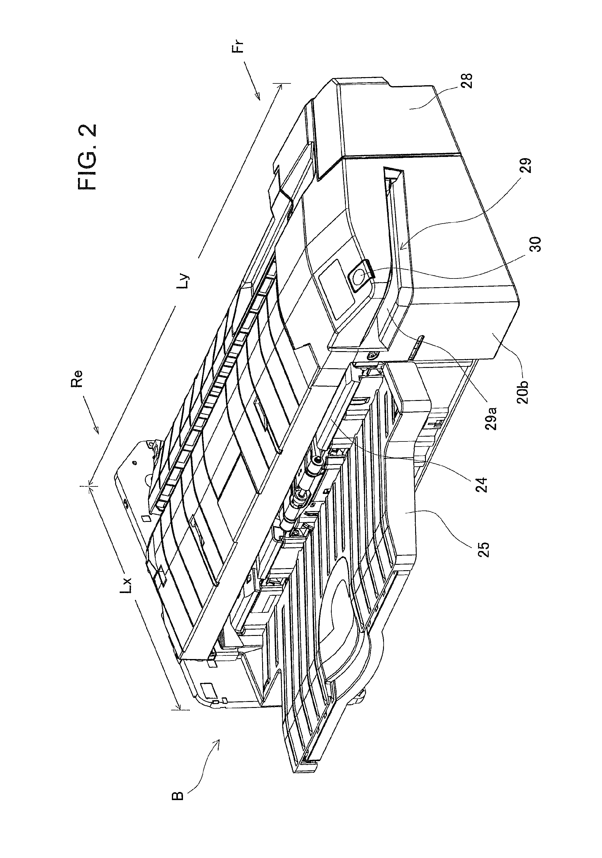
[0043]In the following, the present invention will be described in detail based on preferred embodiments illustrated in the drawings. The present invention relates to a sheet bundle binding processing mechanism which performs a binding process on a collated and stacked sheet bundle with images formed thereon in a later-mentioned image forming system. The image forming system illustrated in FIG. 1 includes an image forming unit A, an image reading unit C, and a post-processing unit B. A document image is read by the image reading unit C. Based on the image data, the image forming unit A forms an image on a sheet. Then, the post-processing unit B (i.e., sheet bundle binding processing apparatus, as the case may be) performs a binding process with the image-formed sheets collated and stacked and stores the sheets on a stack tray 25 at the downstream side.

[0044]The post-processing unit B which will be described later is built in as a unit at a sheet discharge space (stack tray space) 15...


PUM

PropertyMeasurementUnit
angleaaaaaaaaaa
oblique angleaaaaaaaaaa
angleaaaaaaaaaa

Abstract

The purpose of the present invention is to provide a sheet bundle binding processing apparatus capable of providing relatively strong bonding when a plurality of sheets are bound by corrugation-shaped pressurizing faces with nip-pressure deformation and causing less frictional damage on a sheet face when a sheet bundle is introduced to and discharged from the binding unit. The present invention comprises a sheet bundle binding processing apparatus including a processing tray which includes a sheet placement face on which sheets are stacked, a press binding device which bonds mutually overlapped sheets stacked on the processing tray with pressure-bonding deformation, a taking-off device which applies a taking-off force to sheets bound by the press binding device along the sheet placement face for taking off the sheets from the press binding device, and a sheet bundle discharging device by which the sheets taken off from the press binding device by the taking-off device is discharged from the processing tray.

Description

RELATED APPLICATIONS[0001]The present application is based on, and claims priority from, Japanese Application No. JP2013-149859 filed Jul. 18, 2013, the disclosure of which is hereby incorporated by reference herein in its entirety.BACKGROUND OF THE INVENTION[0002]1. Field of the Invention[0003]The present invention relates to a sheet bundle binding processing apparatus which performs a binding process on sheets fed from an image forming apparatus or the like after stacking the sheets into a bundle shape, and relates to improvement of a sheet bundle discharging mechanism with a non-staple binding unit which bonds mutually overlapped sheets with pressure deformation.[0004]2. Description of Related Arts[0005]In general, as a post-processing apparatus, there has been widely known an apparatus which performs a binding process with a binding processing unit after stacking, on a processing tray, sheets fed from an image forming apparatus and stores the sheets on a stack tray at the downst...

Claims


Application Information

Patent Timeline
Patent Type & Authority Patents(United States)
IPC IPC(8): B65H37/04B31F5/02B31F1/07B31F5/00B42C1/12B42B4/00B65H43/00B65H31/38B42B5/00B65H31/20B65H31/26B65H31/30B65H31/34
CPCB31F5/001B31F1/07B65H37/04B31F5/02B42B4/00B42B5/00B42C1/12B65H31/20B65H31/26B65H31/3081B65H31/34B65H31/38B65H43/00G03G2215/00827G03G2215/00852B31F2201/00B65H2301/4212B65H2301/4213B65H2404/1114G03G15/6541
Inventor KUBO, MAMORUNISHIZAWA, SEIJI
Owner COPYER
Learn More