Ore slurry production method and metal refining method

a technology of ore slurry and metal refining, which is applied in the direction of grain treatment, etc., can solve the problems of inability to carry out the transport process using a general-use slurry transporting pump, the viscosity of the resulting ore slurry is too high, and the ore slurry is too large to achieve the effect of reducing the viscosity of the ore slurry, facilitating the operation, and facilitating the operation

Active Publication Date: 2016-08-09
SUMITOMO METAL MINING CO LTD
View PDF20 Cites 2 Cited by
  • Summary
  • Abstract
  • Description
  • Claims
  • Application Information

AI Technical Summary

Benefits of technology

[0032]The present invention produces an ore slurry that makes it possible to suppress a rise in the viscosity of the ore slurry, and consequently to prevent a failure in transporting the ore slurry to the next process. In accordance with this ore slurry, it is possible to transport the ore slurry efficiently to a metal refining process or the like, without the necessity of preparing a new facility or the like, and consequently to carry out the operation efficiently.

Problems solved by technology

However, the above-mentioned conventional ore treatment tends to form fine ore particles due to fluctuations of the grain size of the raw material ores to be loaded and degrees of pulverization in the pulverizing process, with the result that the viscosity of the resulting ore slurry tends to become too high.
It has been known that when such an ore slurry is used, the viscosity of the ore slurry becomes too high.
Therefore, in the case when the yield stress of the ore slurry becomes high as described above, and exceeds, for example, 200 Pa, a problem is raised in that the transporting process cannot be carried out by using a general-use slurry transporting pump.
Such a problem causes a situation in which the plant has to be temporarily stopped, resulting in a serious reduction in operation efficiency.
In order to prevent such a viscosity rise in the ore slurry, a method is proposed in which “a shearing pump” that utilizes an effect for reducing the viscosity in the slurry (Shear Thinning effect), by applying a shearing force thereto several times prior to transporting the slurry; however, this method undesirably requires expensive facilities, and causes a complicated facility structure, and high costs for introducing the method as well as high maintenance costs.
This is because when the yield stress of the ore slurry becomes such a high degree as to exceed, for example, 200 Pa, in the initial stage after being loaded into a heat exchanger, the ore slurry tends to adhere to its wall surfaces and members, and anchored thereon without being allowed to flow, resulting in clogging of the device in the worst case.
On the other hand, for example, in order to avoid the grain size of the ores to be loaded from becoming too small, a method is easily proposed in which a process for removing fine ore particles is newly installed as the final stage of the pulverizing / classifying step; however, high costs are required for introducing such a facility.
Moreover, the amount of ores to be rejected from the pulverizing / classifying step increases to cause a problem in that resources are not effectively utilized.
Moreover, as the viscosity adjusting method, for example, as described in Patent Document 4, a method or the like is proposed in which in order to allow muddy water whose viscosity is unknown to exert a predetermined viscosity, the added water amount is adjusted; however, this technique relates to an adjusting method for the viscosity of muddy water for use in a shield engineering technique, a pile engineering technique, a fluidization treatment engineering technique, an underground continuous wall engineering technique and the like in the construction field, and it is difficult to apply this method to the viscosity adjusting method for an ore slurry after having been dehydrated.

Method used


Image

  • Ore slurry production method and metal refining method
  • Ore slurry production method and metal refining method
  • Ore slurry production method and metal refining method

Examples


example 1

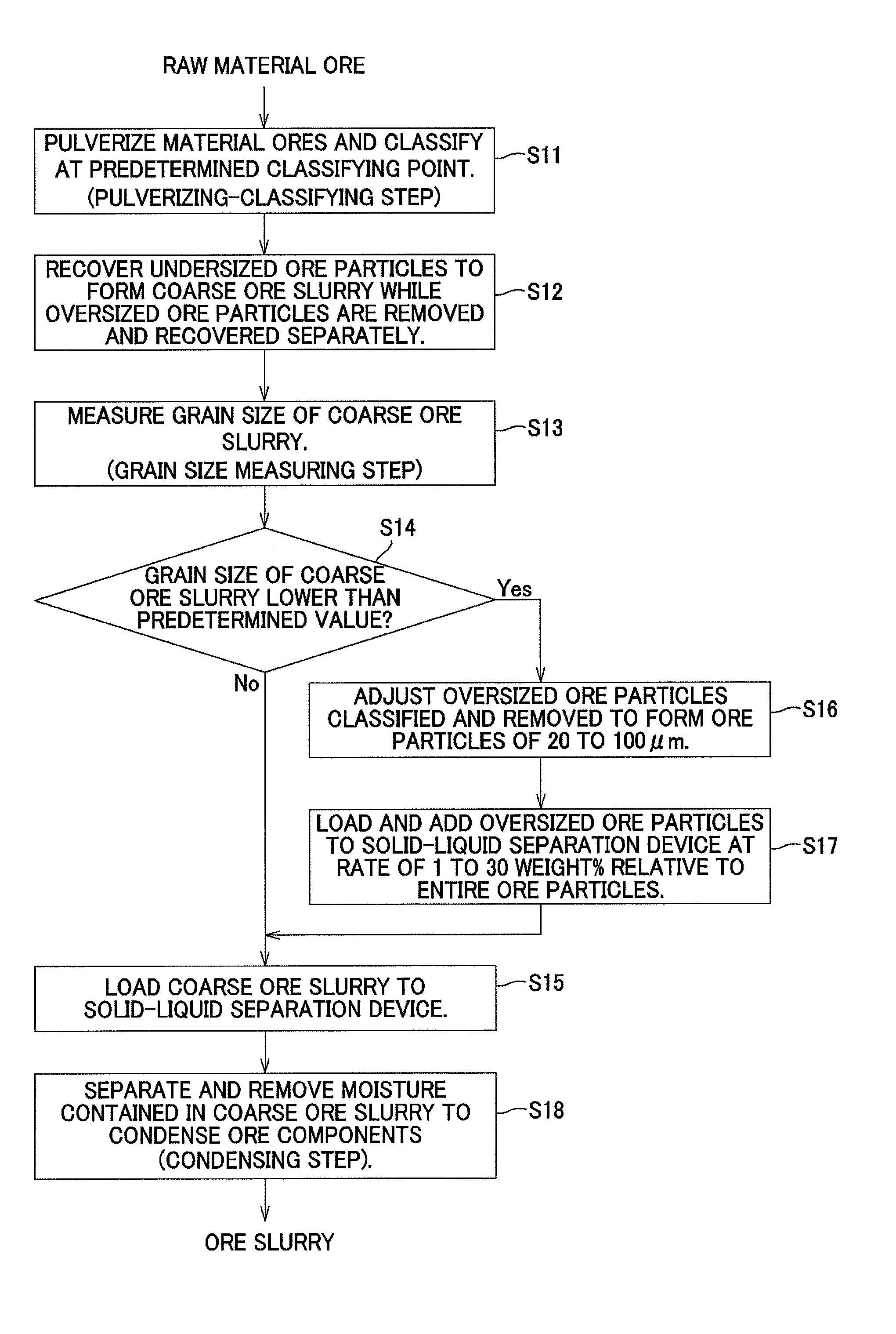
[0121]In an ore slurry producing step for use in recovering nickel and cobalt from nickel oxide ores serving as raw material ores, by a high-temperature pressure acid leaching method (HPAL method) by the use of sulfuric acid, first, nickel oxide ores were pulverized by using a general-use pulverizer. Then, the pulverized nickel oxide ores were classified by using a sieve with a mesh having an opening of 1.4 mm. The undersized ore particles classified by the classifying process were recovered so that a coarse ore slurry containing 100 g / L of solid components was produced. On the other hand, the classified oversized ore particles were removed and recovered in a separated manner.

[0122]Next, the grain size of the coarse ore slurry was measured by using a Microtrack Device (9320-X100, made by Nikkiso Co., Ltd.). In this case, the grain size of the coarse ore slurry was measured to obtain a volume-average diameter (mv) as a measured value. As a result, the particle diameter of the coarse ...

example 2

[0127]By carrying out a pulverizing / classifying process on nickel oxide ores serving as raw material ores in the same manner as in example 1, a coarse ore slurry was obtained, and the same processes as those of example 1 were carried out so that a similar ore slurry was obtained except that when the grain size of the resulting coarse ore slurry was measured, the particle diameter of the coarse ore slurry was 14.26 μm.

[0128]The yield stress of the resulting ore slurry was measured by using a rheometer in the same manner as in example 1. As a result, the yield stress of the ore slurry was 160 Pa so that it was possible to transport the slurry to the next leaching step by using a general-use transporting pump, without causing any transporting failure, etc.

[0129]Moreover, in the succeeding leaching step by the use of the HPAL method also, the nickel leaching rate was 93.2%, which was a satisfactory result.

example 3

[0130]By carrying out the pulverizing / classifying process on nickel oxide ores serving as raw material ores in the same manner as in example 1, a coarse ore slurry was obtained, and the same processes as those of example 1 were carried out so that a similar ore slurry was obtained except that when the grain size of the resulting coarse ore slurry was measured, the particle diameter of the coarse ore slurry was 18.26 μm.

[0131]The yield stress of the resulting ore slurry was measured by using a rheometer in the same manner as in example 1. As a result, the yield stress of the ore slurry was 150 Pa so that it was possible to transport the slurry to the next leaching step by using a general-use transporting pump, without causing any transporting failure, etc.

[0132]Moreover, in the succeeding leaching step by the use of the HPAL method also, the nickel leaching rate was 93.0%, which was a satisfactory result.


PUM

PropertyMeasurementUnit
yield stressaaaaaaaaaa
grain sizeaaaaaaaaaa
particle sizeaaaaaaaaaa

Abstract

Disclosed is a method for producing an ore slurry that can suppress a rise in the viscosity of the ore slurry and consequently prevent a failure in transporting the slurry, and also to provide a metal refining method utilizing such a slurry producing method. The present invention includes: a pulverizing / classifying step of pulverizing raw material ores and classifying the resulting ores at a predetermined classifying point so that oversized ore particles are removed so as to obtain a coarse ore slurry composed of undersized ore particles; a grain size measuring step of measuring the grain size of the resulting coarse ore slurry; and an ore slurry condensing step of loading the coarse ore slurry to a solid-liquid separation device and separating and removing moisture contained in the coarse ore slurry therefrom so as to condense ore components.

Description

FIELD OF THE INVENTION[0001]This invention relates to a method of producing an ore slurry and a metal refining method, and more particularly concerns a method of producing an ore slurry that can suppress a rise in the viscosity of the ore slurry and a metal refining method to which such a method of producing an ore slurry is applied.[0002]The present application asserts priority rights based on JP Patent Application 2011-242308 filed in Japan on Nov. 4, 2011. The total contents of disclosure of the Patent Application of the senior filing date are to be incorporated by reference into the present Application.BACKGROUND OF THE INVENTION[0003]In recent years, as a refining method for recovering nickel and cobalt from nickel oxide ores containing nickel and cobalt respectively about 1.0 to 2.0% and about 0.1 to 0.5% relative to the total amounts thereof, a high-temperature pressure acid leaching method (hereinafter, referred to sometimes as HPAL Method: high pressure acid leach), which i...

Claims


Application Information

Patent Timeline
Patent Type & Authority Patents(United States)
IPC IPC(8): B02C19/00C22B23/00C22B1/00C22B3/00
CPCC22B1/00C22B23/005C22B23/0407B02C19/00Y02P10/20
Inventor MITSUI, HIROYUKISHIBAYAMA, KEISUKESHOJI, HIROFUMIHIGAKI, TATSUYAKYODA, YOJINAKAI, OSAMU
Owner SUMITOMO METAL MINING CO LTD
Why Eureka
Try Eureka