Centring means in a rotary tong
a technology of centring means and rotary tongs, which is applied in the direction of drill bits, wrenches, screwdrivers, etc., can solve the problems of difficult to obtain a precise arrangement, difficult to obtain good control of the positioning of hydraulically controlled gripping devices, and large work force, etc., to achieve simple mechanical positioning and holding
- Summary
- Abstract
- Description
- Claims
- Application Information
AI Technical Summary
Benefits of technology
Problems solved by technology
Method used
Image

Examples
first embodiment
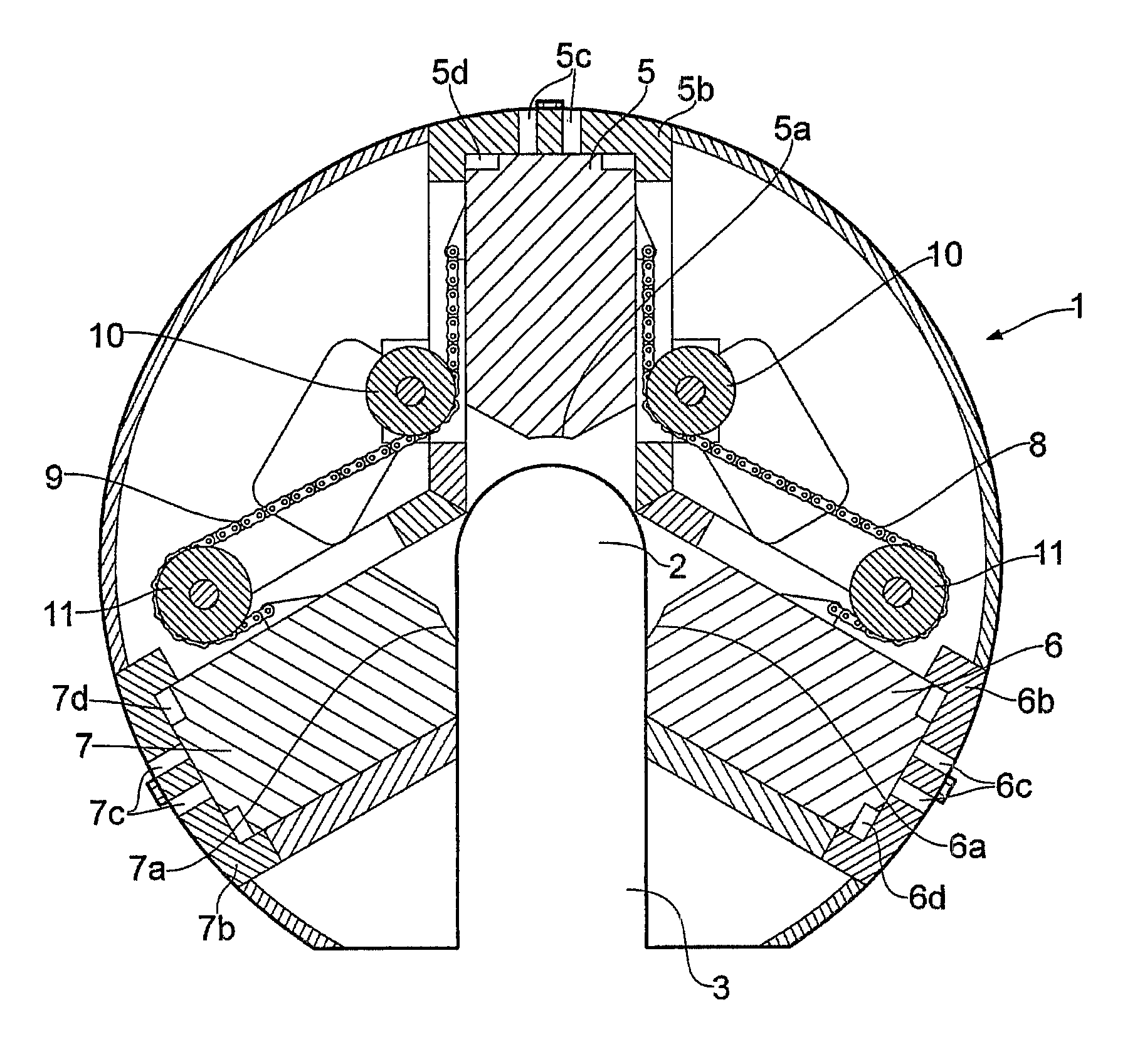
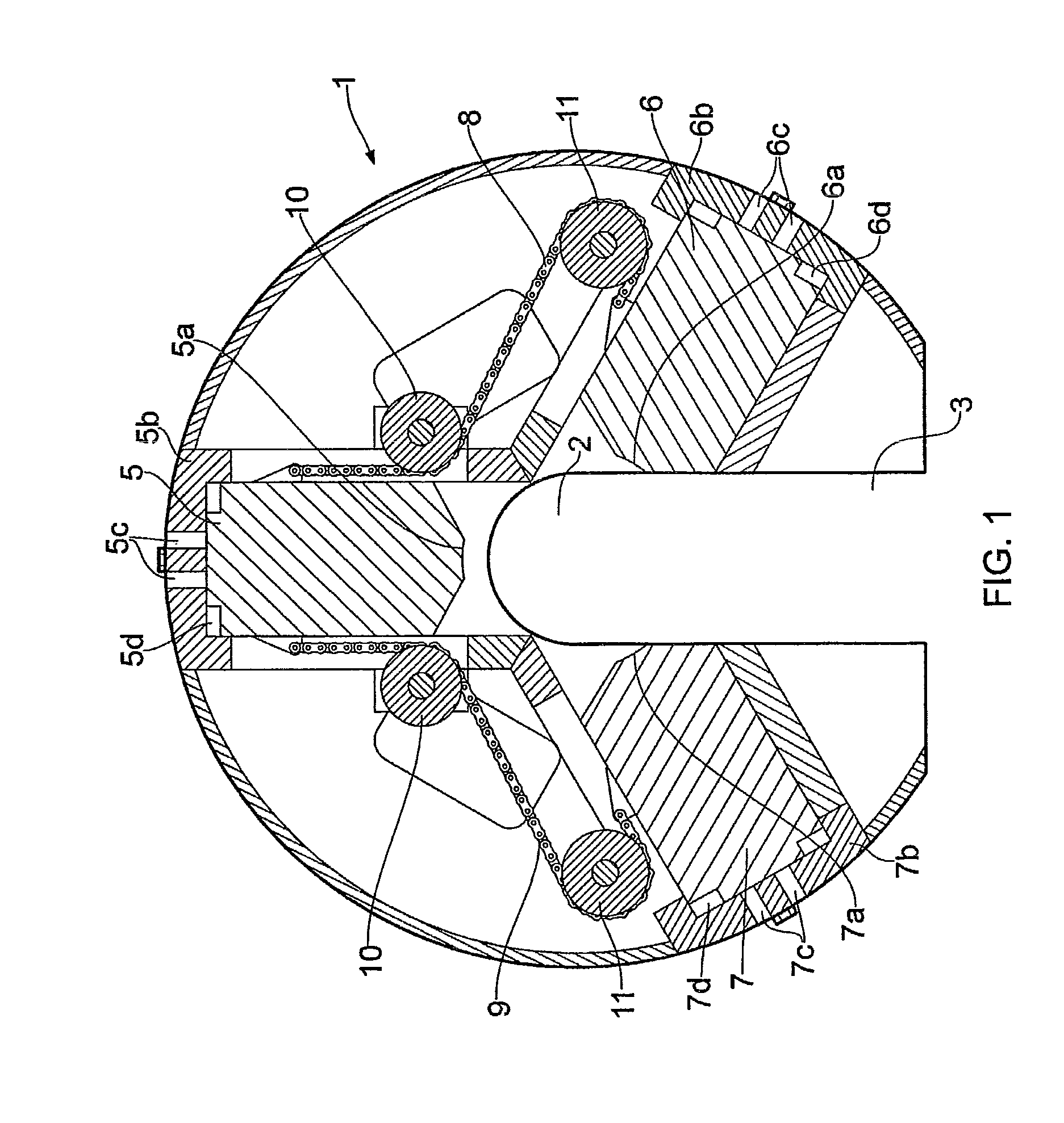
[0056] shown in FIG. 1, the first roller means 10 are so positioned that the chains 8, 9 are positioned parallel to the first gripping device 5. The chain portion between the first gripping device 5 and first roller means 10 will thus be given a movement in a direction that coincides with the movement of first gripping device 5, and this configuration provides for effective transmission of pulling force to the first gripping device. The chains 8, 9 are passed onwards from the first roller means 10 to the second roller means 11, each chain being passed substantially a half turn around the second roller means 11 such that the chain at the run-out from the second roller means 11 is directed in a direction that is opposite the direction at the run-in onto the second roller means 11. The chains 8, 9 are passed from the second roller means 11 to attachment on respectively the second and the third gripping device 6, 7. As a result of the chain being deflected such that the movement is give...
third embodiment
[0061]In the pipe clamping device 1 that is shown in FIG. 3, the arrangement comprises two gripping devices, a first roller means 10 and a first chain 8. The first end 8 of the chain is attached to the first gripping device 5 and its second end is attached to the second gripping device 6. Movement of the first gripping device 5 in towards the tubular centre is transmitted as a pulling force in the chain to the second gripping device 6 so as to secure simultaneous movement of the gripping devices 5, 6 in towards the tubular centre 2 similar to that described in connection with the discussion of the other embodiments
fourth embodiment
[0062]FIG. 4 shows the pipe clamping device 1, where the pipe clamping device 1, in addition to the set comprising a first roller means 10a and a first chain 8a as shown in FIG. 3, also further comprises a first roller means 10b and a second chain 8b. This arrangement allows movement of the first gripping device 5 to be transmitted as a pulling force via the chain 8 to the second gripping device 6 and movement of the second gripping device 5 to be transmitted as a pulling force in the chain 8 to the first gripping device 6. In this way, it is ensured that both gripping devices are given a reciprocal limitation of movement in towards the tubular centre as movement of one of the gripping devices is dependent on the movement of the other gripping device.
PUM
 Abstract
Description
Claims
Application Information
 - R&D
- Intellectual Property
- Life Sciences
- Materials
- Tech Scout
- Unparalleled Data Quality
- Higher Quality Content
- 60% Fewer Hallucinations
Browse by: Latest US Patents, China's latest patents, Technical Efficacy Thesaurus, Application Domain, Technology Topic, Popular Technical Reports.
© 2025 PatSnap. All rights reserved.Legal|Privacy policy|Modern Slavery Act Transparency Statement|Sitemap|About US| Contact US: help@patsnap.com