
Packaged propellant air-induced variable thrust rocket engine

a propellant and variable thrust technology, applied in the direction of machines/engines, pressure gas generation, weapons, etc., can solve the problems of unoxidized aluminum, oxidized outer surface cracks, and particle heating beyond melting point, and achieve excellent heat release, reduced cost of heat source, and rapid heating of particle beyond melting point

Active Publication Date: 2016-08-09
INNOVATIVE DEFENSE
View PDF10 Cites 0 Cited by
  • Summary
  • Abstract
  • Description
  • Claims
  • Application Information

AI Technical Summary

Benefits of technology

The invention uses a process called aerodynamic compression to heat and accelerate air using small particles of fuel that can be ignited by light. These particles, such as nano-sized aluminum, release energy quickly and can be directed to produce thrust in a pulsed fashion. This technology allows for efficient use of fuel and cooler exhaust, and can use different fuel mixtures for different needs, such as cruise or maximum power.

Problems solved by technology

Light energy is absorbed but can not be radiated back out of the particle, causing very rapid heating of the particle beyond its melting point.
When the particle melts, its oxidized outer surface cracks open and exposes unoxidized aluminum.

Method used


Image

  • Packaged propellant air-induced variable thrust rocket engine
  • Packaged propellant air-induced variable thrust rocket engine
  • Packaged propellant air-induced variable thrust rocket engine

Examples


Embodiment Construction

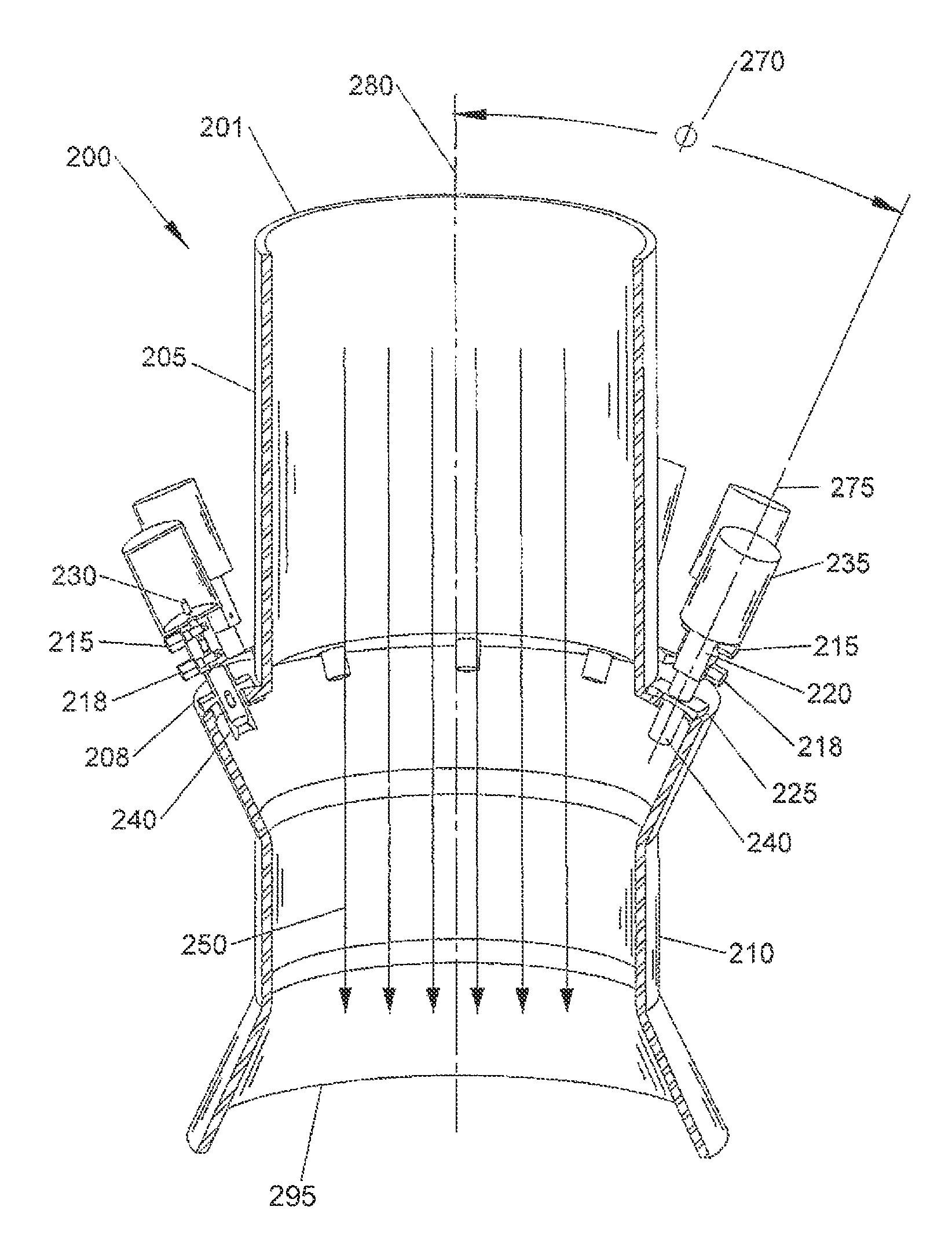
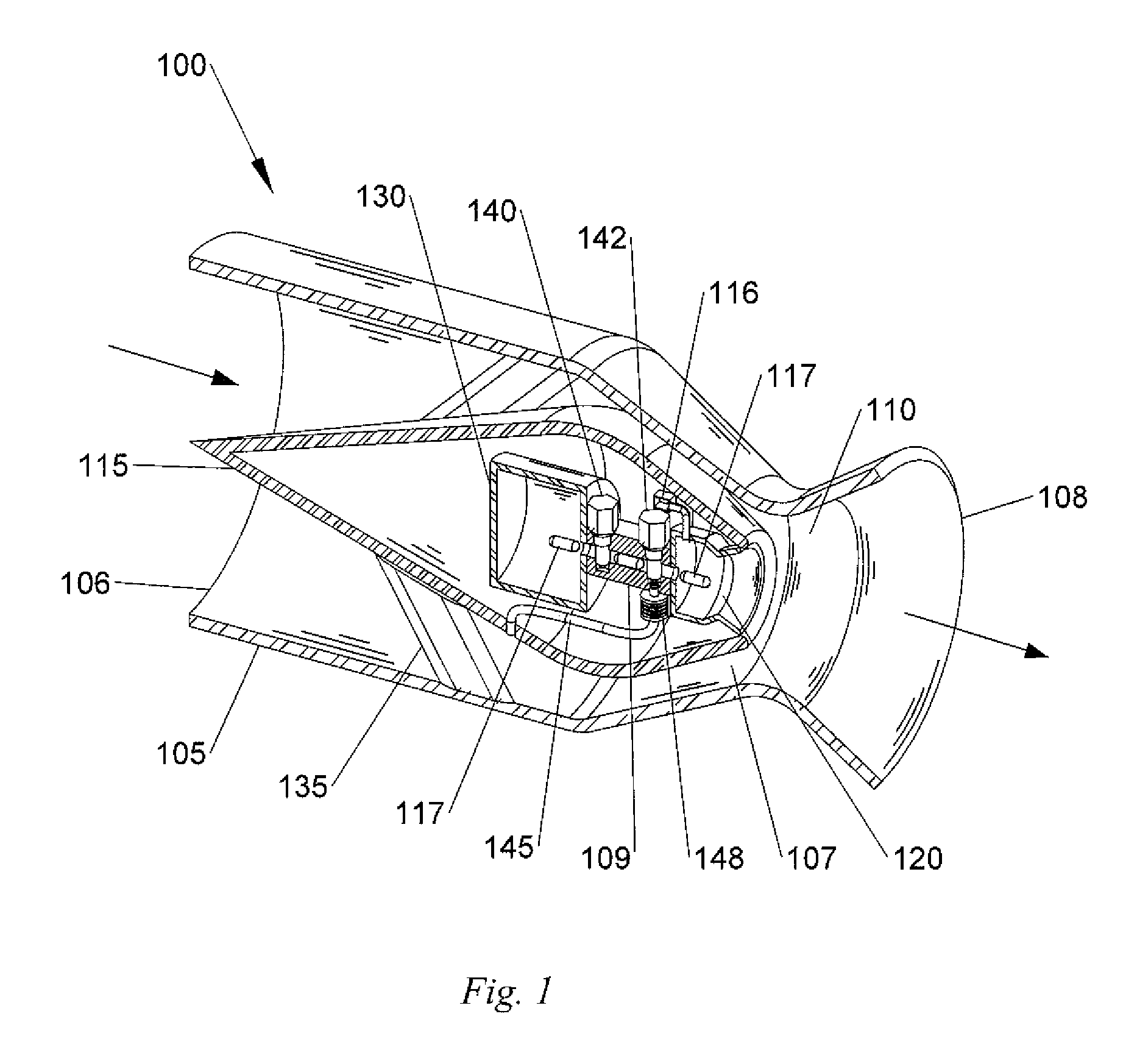
[0027]FIG. 1 shown an air-induced rocket engine 100 using the teachings of the present invention. Air enters through front airflow inlet 106 and is divided by a central air divider 115 which supported in the airflow housing 105 by support struts 135. Located inside the central air divider 115 is an Energetic Fuel Packet (EFP) 117 storage compartment 130. This storage compartment can be replaced or supplemented by a separate storage area located outside the housing 105 with a connecting delivery tube not shown.

[0028]When thrust is needed, a backflow prevention valve 140 opens and an EFP 117 is injected through the air / fuel delivery manifold 109 into the combustion chamber 120. Photonic energy from a strobe light 116 or other means ignites the nano-aluminum particles contained in the water and the EFP 117, while in the combustion chamber 120. Very high temperature is created by the nano-energetic particles that convert the surrounding water to superheated steam, and also igniting othe...


PUM


Abstract

This invention is a packaged propellant air-induced variable thrust rocket engine that has a vast number of uses and applications for this invention. The primary purpose of the device described here is to provide a light weight, torque and vibration free thrust generator for the propulsion of aircraft. This device will facilitate the fabrication of very light weight aircraft because of the lack these forces. This device can also be used anywhere high velocity air flow and or the resulting thrust is needed. The invention uses aerodynamic principles to compress and accelerate the incoming air, prior to it being heated and accelerated by a short duration burst of thermal and kinetic energy from discrete packets of a mixture of oxidizable fuels. The heated and accelerated air then expands as it travels thru the device providing thrust.

Description

RELATED APPLICATION DATA[0001]This application is related to Provisional Patent Application Ser. No. 61 / 338,816 filed on Feb. 24, 2010, and priority is claimed for this earlier filing under 35 U.S.C. §119(e). The Provisional Patent Application is also incorporated by reference into this patent application.TECHNICAL FIELD OF THE INVENTION[0002]The present invention relates to air-induced variable thrust rocket engines.BACKGROUND AND PRIOR ART OF THE INVENTION[0003]Although the Wright Brothers are credited with the first powered flight, even ancient man's dreams and ambitions have shown a fascination with the thought of leaving the ground and defying gravity. Logic would dictate the idea of flight was there in ancient times, I would think from observation of birds. What was missing for ancient man was a source of propulsion and materials strong and light enough. The idea of air passing over a flat surface, edge on, would also have been obvious from the observation of birds, leaves, an...

Claims


Application Information

Patent Timeline
Patent Type & Authority Patents(United States)
IPC IPC(8): F02K9/62
CPCF02K9/62
Inventor MUNSON, JR., DAVID MURRAYCOLLIER, NICHOLAS
Owner INNOVATIVE DEFENSE
Learn More