
Pumping device

a pumping device and centrifugal technology, applied in the direction of non-positive displacement pumps, liquid fuel engines, mechanical equipment, etc., can solve problems such as unbalanced thrust, and achieve the effects of reducing shaft vibration, improving efficiency, and quiet operation

Active Publication Date: 2016-08-09
SMITH ANDREW
View PDF9 Cites 0 Cited by
  • Summary
  • Abstract
  • Description
  • Claims
  • Application Information

AI Technical Summary

Benefits of technology

This patent describes a device that mixes fluids using a casing and a sinusoidal impeller. The device maintains a stable flow output and is quieter and more efficient than other mixers. The impeller's design reduces vibrations and interferences, maximizing power transfer and making it more compact. Overall, this device is advantageous for mixing fluids in industrial applications.

Problems solved by technology

However, small capacity centrifugal pumps are usually of a single-suction design, which imposes an unbalanced thrust of the shaft thrust bearing that has to be taken into account, as well as unbalanced forces on the pump which may cause vibrations.

Method used


Image

  • Pumping device
  • Pumping device
  • Pumping device

Examples


Embodiment Construction

[0034]There will now be described by way of example a specific mode contemplated by the inventors. In the following description numerous specific details are set forth in order to provide a thorough understanding. It will be apparent however, to one skilled in the art, that the present invention may be practiced without limitation to these specific details. In other instances, well known methods and structures have not been described in detail so as not to unnecessarily obscure the description.

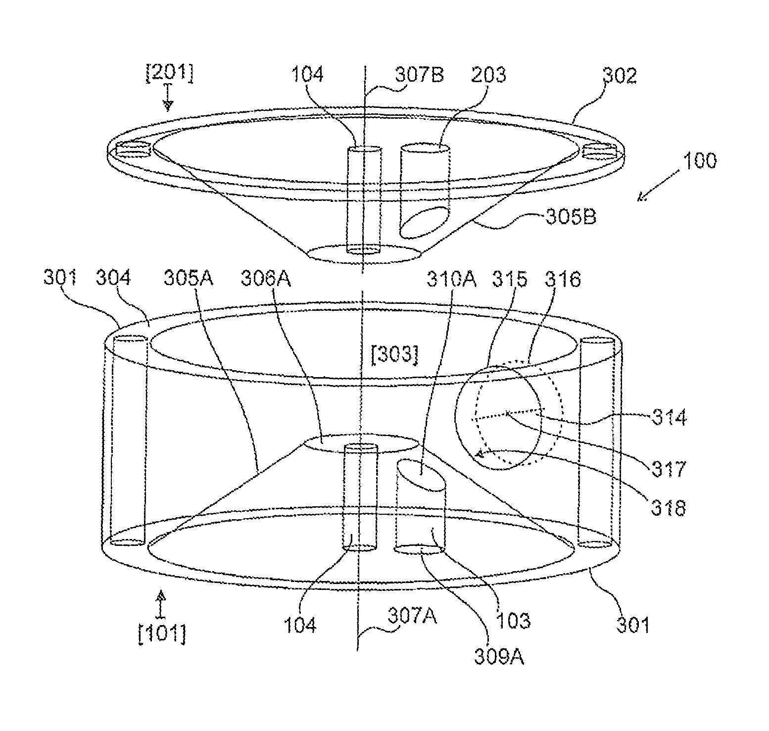
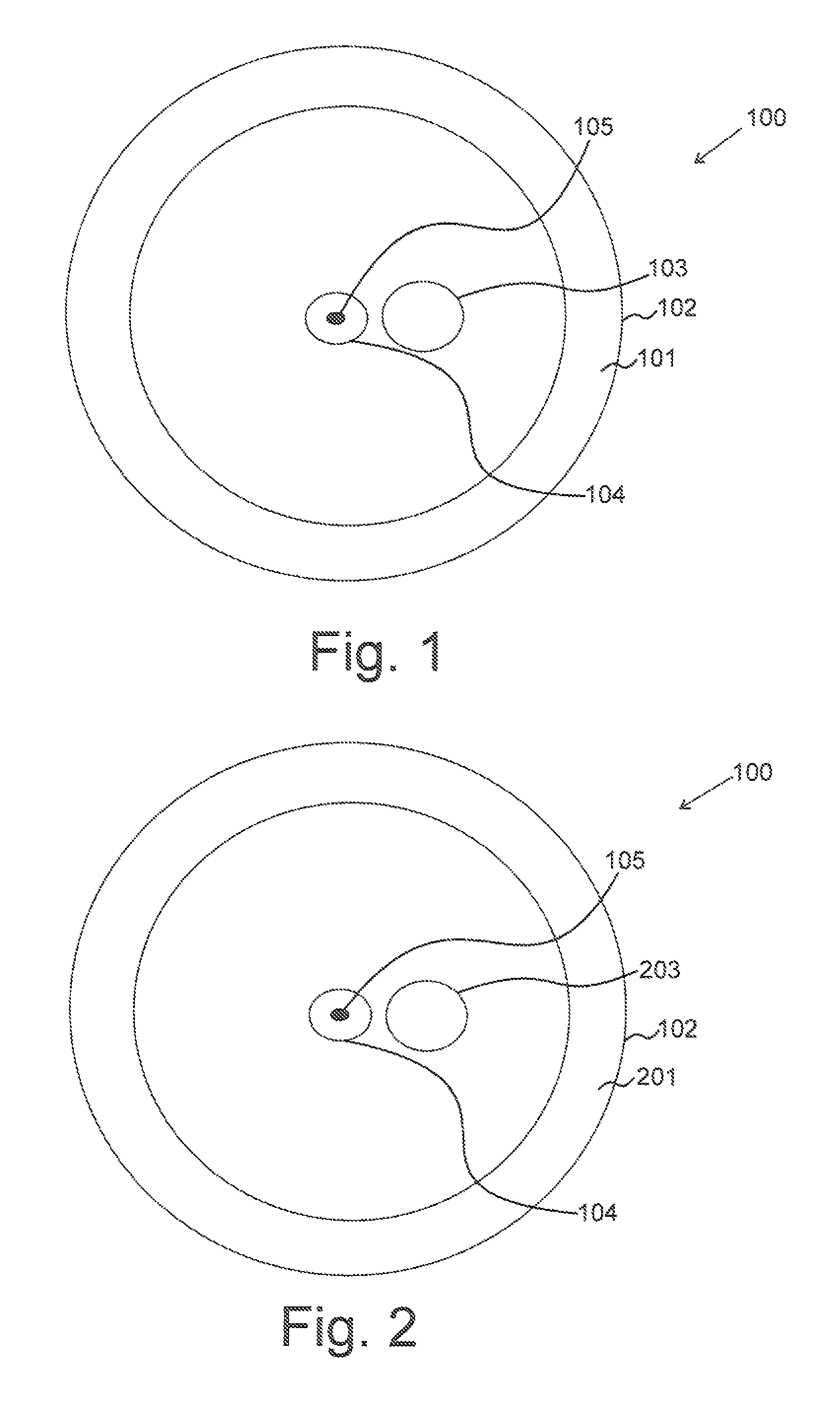
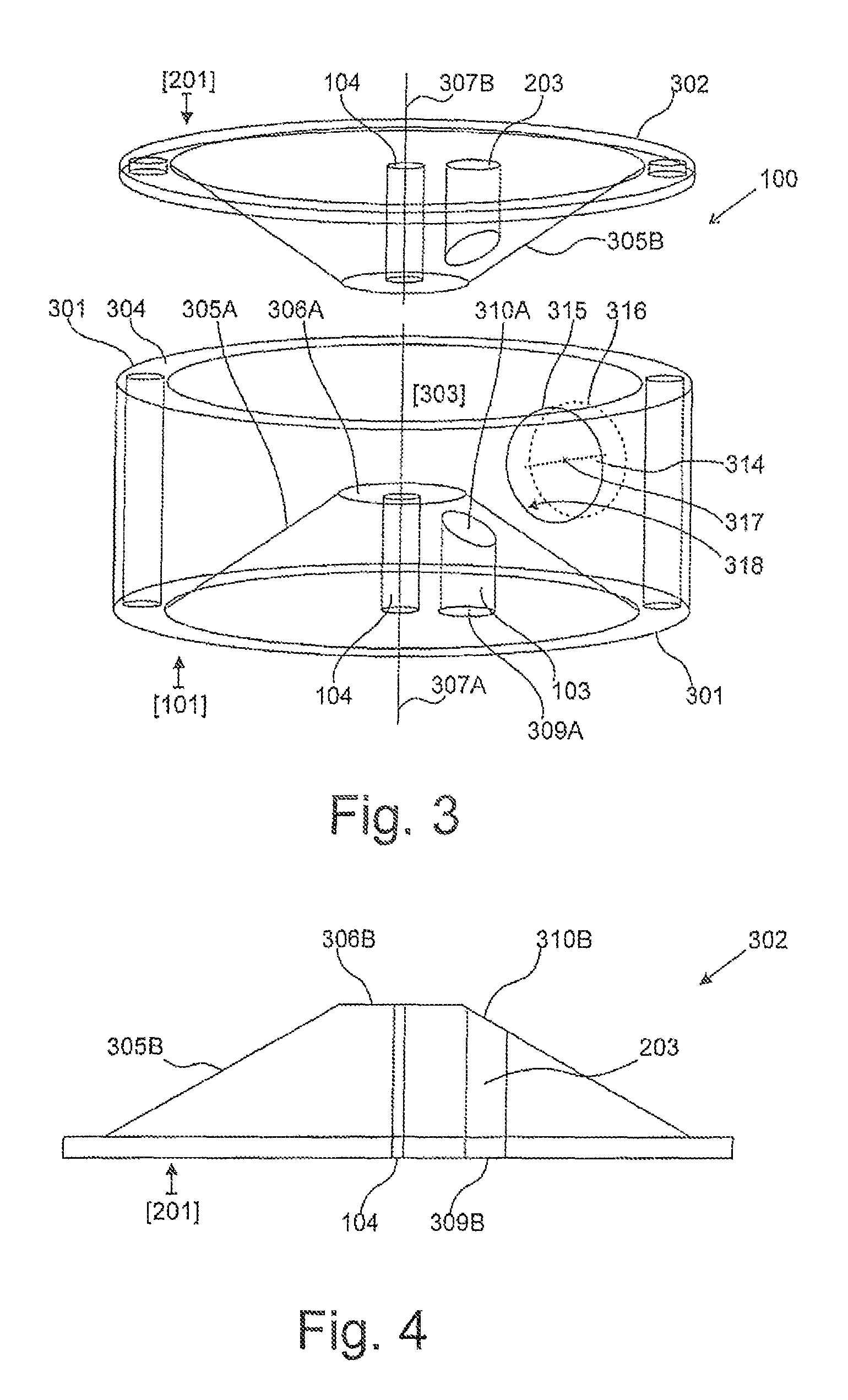
[0035]With reference to FIG. 1, there is shown a top view of a first side 101 of a casing 100 for a pump according to a first embodiment of the present invention. The casing 100 comprises a substantially circular body 102 having a first radial inlet 103 therein, which is located proximate a transversal aperture 104. The aperture 104 is co-axial with the geometrical centre 105 of the body 102 and extends through both sides of the casing 100.

[0036]With reference to FIG. 2, there is shown a top v...


PUM


Abstract

A pump is disclosed, with a casing comprising a substantially circular body having at least two radial inlets, at least one peripheral outlet and a transversal aperture. The casing further comprises a substantially circular impeller mounted within the body for rotation about the aperture. The impeller has a substantially uninterrupted sinusoidal profile. A pumping system and a method of pumping are also disclosed, which use the pump configuration.

Description

FIELD OF THE INVENTION[0001]The present invention relates to centrifugal pumping devices. More particularly, the present invention relates to mixed flow pumps.BACKGROUND OF THE INVENTION[0002]Centrifugal pumping devices are rotodynamic pumping devices which use a rotating impeller within a casing for increasing the pressure and flow rate of a fluid within a fluid conveying network. In centrifugal pumps, a fluid is fed, from an upstream piping system, into the pump casing along or near to the rotating axis of the impeller and is accelerated by the impeller, flowing radially or axially outward into a diffuser or volute chamber, which the fluid exits into a downstream piping system. Rotodynamic pumping devices are typically used for large discharge through smaller heads, and several different types of centrifugal pumps are known, which include radial flow pumps, axial flow pumps and mixed flow pumps.[0003]Mixed flow pumps combine the characteristics of radial and axial flow pumps, wher...

Claims


Application Information

Patent Timeline
Patent Type & Authority Patents(United States)
IPC IPC(8): F01D1/00F04D7/04F04D1/00F04D29/22F04D29/24
CPCF04D1/006F04D7/04F04D29/2216F04D29/245F04D29/2233F04D29/242
Inventor SMITH
Owner SMITH ANDREW
Features
  • Generate Ideas
  • Intellectual Property
  • Life Sciences
  • Materials
  • Tech Scout
  • Unparalleled Data Quality
  • Higher Quality Content
  • 60% Fewer Hallucinations
Learn More