

Valve element structure of proportional reversing valve
A proportional reversing valve and valve core technology, applied in valve devices, multi-port valves, sliding valves, etc., can solve the problems of reduced overcurrent pressure and high flow control requirements, and achieve large overflow, stable flow output and stable operation. Effect
- Summary
- Abstract
- Description
- Claims
- Application Information
AI Technical Summary
Problems solved by technology
Method used
Image

Examples
Embodiment Construction
[0027] The spool structure of the proportional reversing valve described in the present invention can be made of the following materials, and is not limited to the following materials, such as common components such as spool, hydraulic matching system, and electric control device.
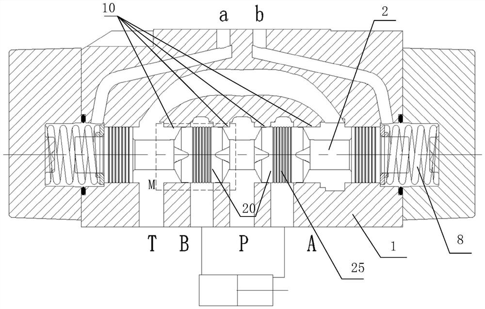
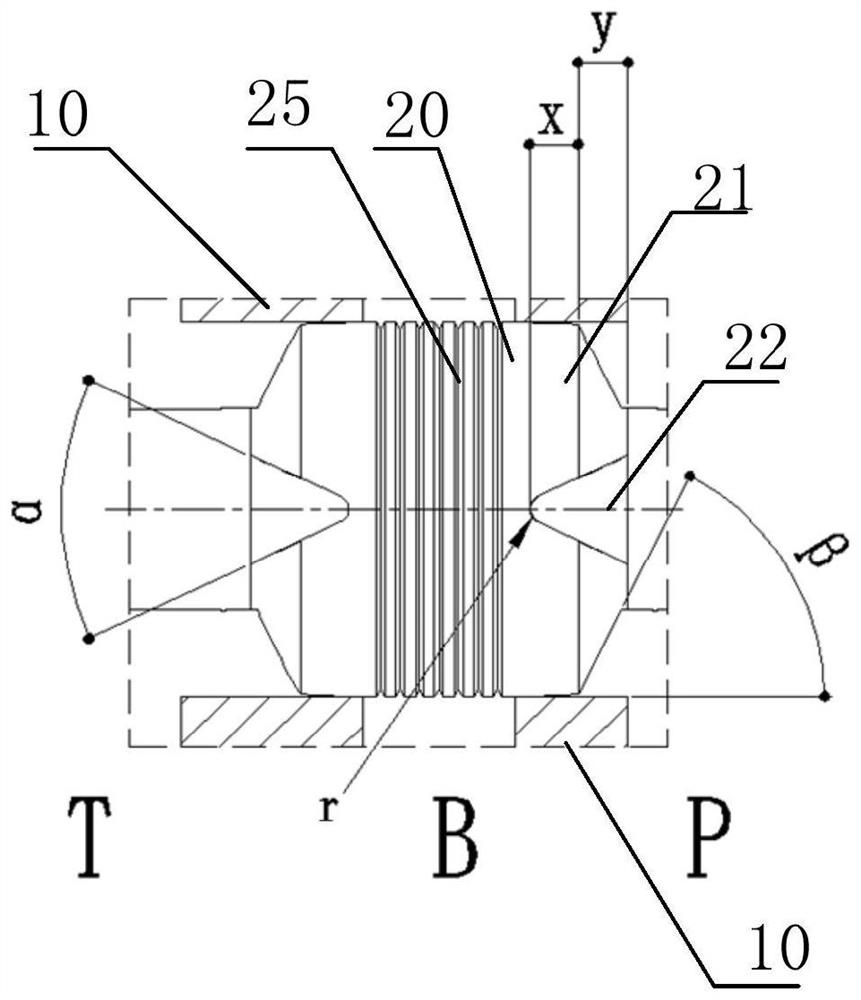
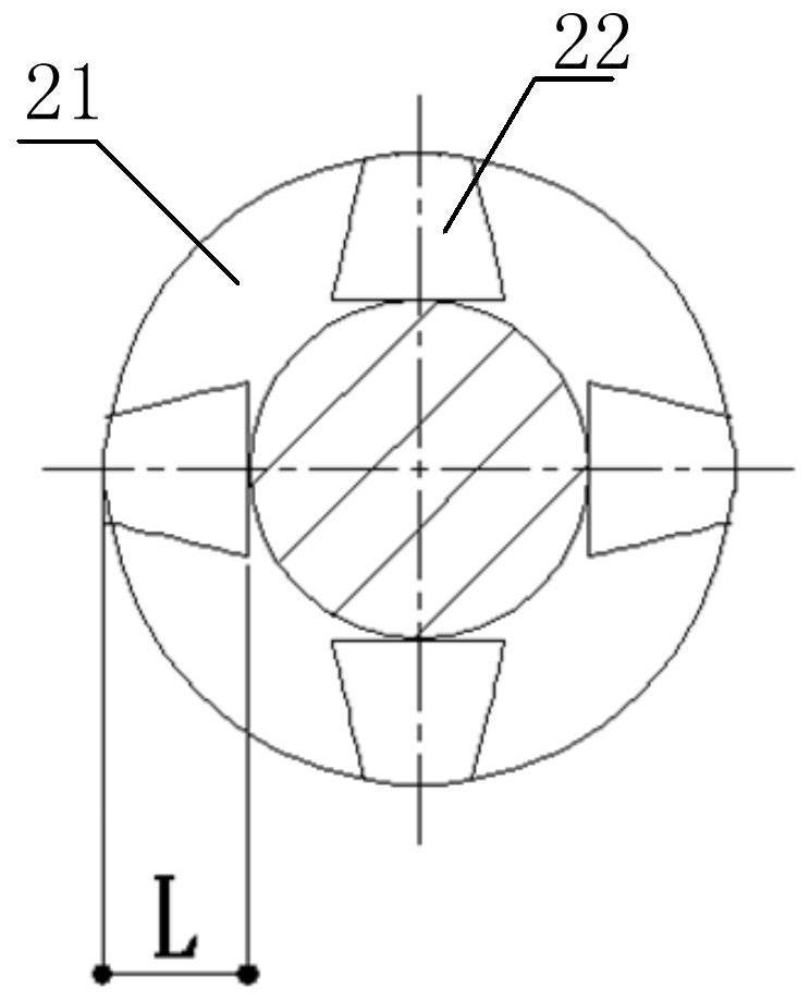
[0028] figure 1 It is a schematic diagram of the cross-sectional structure of the valve core structure of the proportional directional valve in the embodiment of the present invention in the neutral state; figure 2 for figure 1 Partial enlarged schematic diagram of middle M; this embodiment combines image 3 with Figure 4 Be explained.
[0029] The spool structure of the proportional reversing valve in the embodiment of the present invention is slidably installed in the housing 1, and the housing 1 is provided with a high-pressure oil port P and at least one working oil port (A and B). The housing 1 is provided with a slide hole 10, the valve core 2 is sleeved in the slide hole 10 and seals t...
PUM
| Property | Measurement | Unit |
|---|---|---|
| Angle | aaaaa | aaaaa |
Abstract
Description
Claims
Application Information