Receiver for wireless charging system
a wireless charging and receiver technology, applied in the direction of loop antennas with ferromagnetic cores, electrochemical generators, transportation and packaging, etc., can solve the problems of user trouble, terminal jacks or terminals can be damaged, and the user can suffer considerable troubles and inconvenience, so as to enhance the efficiency of magnetic fields and enhance reception efficiency
- Summary
- Abstract
- Description
- Claims
- Application Information
AI Technical Summary
Benefits of technology
Problems solved by technology
Method used
Image
Examples
embodiment 1
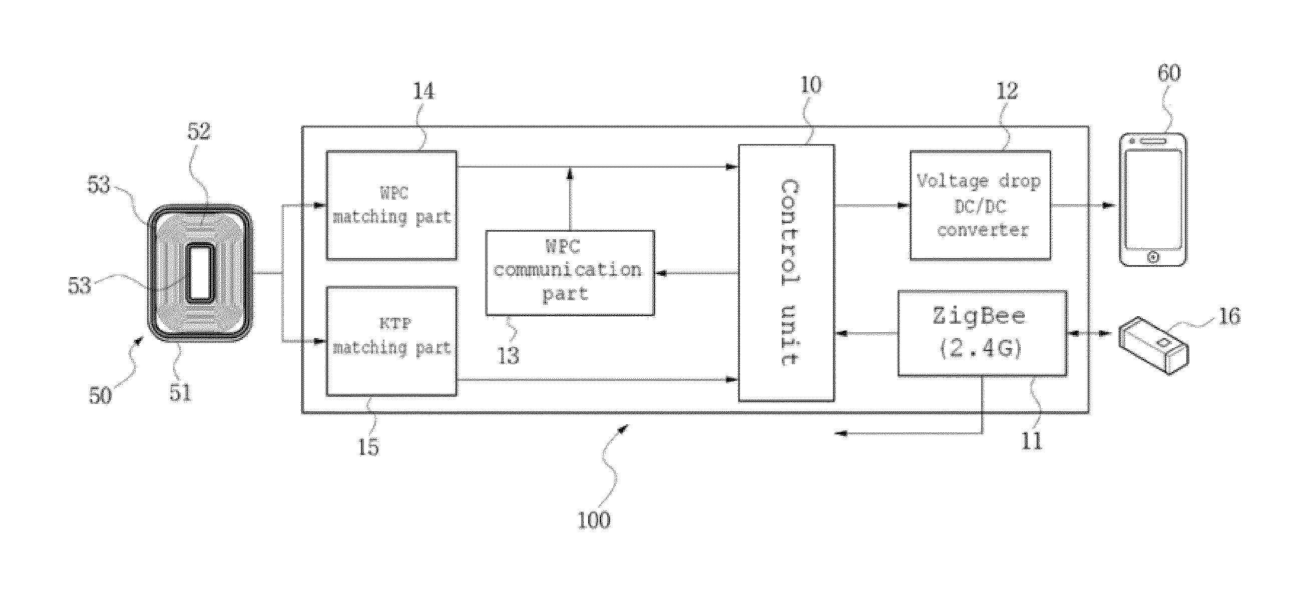
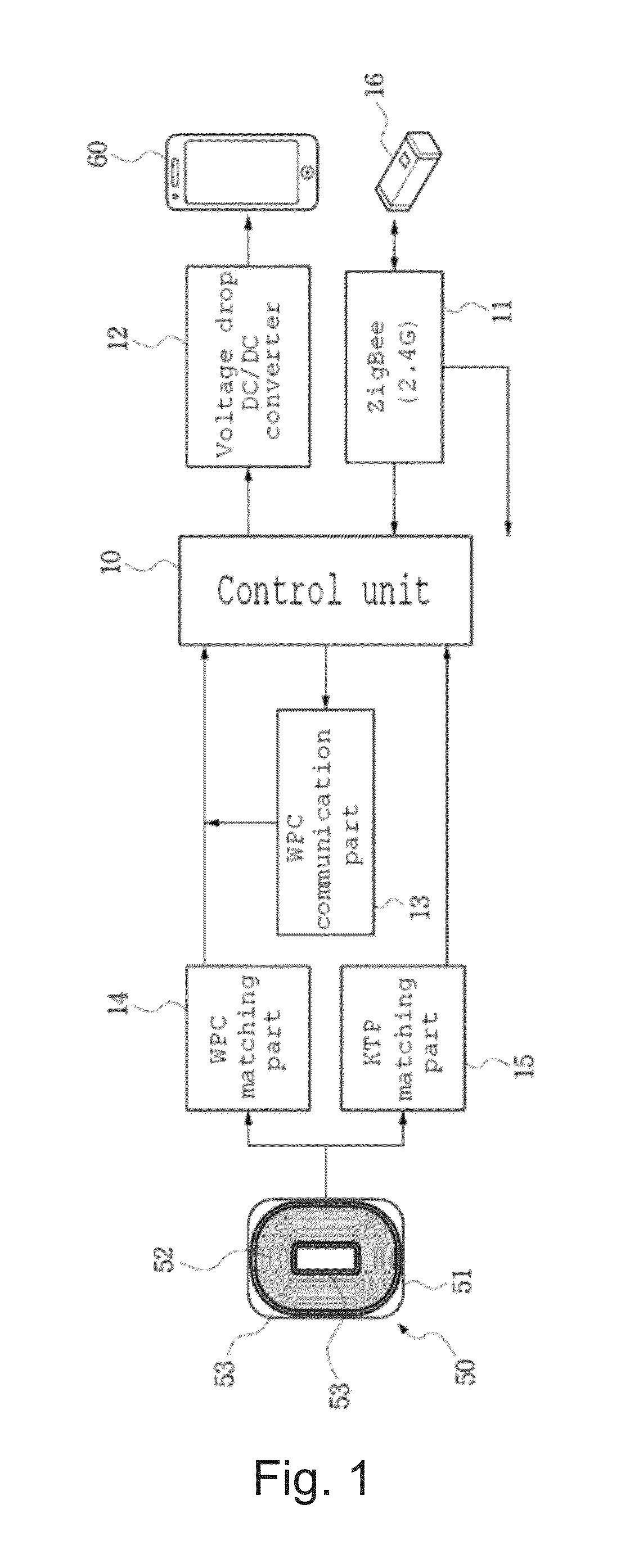
[0047]FIG. 1 is a block diagram showing a reception unit of a wireless charging system of the present invention.
[0048]Generally, a wireless charging system is configured of a transmission unit for transmitting power energy and a reception unit for receiving the power energy, and the transmission unit periodically drives a sensor to sense a predetermined signal and determines whether or not a charge request signal is sensed. When a charge request signal is sensed, a power transmission unit of the transmission unit is turned on. Then, the transmission unit confirms battery voltage of the receiving side through a signal of the reception unit, and if a charge enable state is confirmed, transmission of power is performed.
[0049]At this point, if the wireless charging system enters into the above state, the reception unit receives the power energy, and power is charged into the battery of the reception unit. That is, the block diagram of FIG. 1 shows an effective design structure of the re...
embodiment 2
[0070]FIG. 8 is a view illustrating the principle of a wireless charger.
[0071]FIG. 8 shows a general structure of a wireless charger for supplying power energy. First, a reception unit 200 has a structure of connecting the antenna loop coils 52 and 53 to a condenser C in series, and a transmission unit 300 also has a structure of connecting an antenna loop coil 31 to a condenser C in parallel. The only difference is that the transmission unit 300 is further provided with a resonance filter, and the resonance filter is configured as a structure of connecting the coil 62 and the condenser C in series. At this point, it is apparent that the series and parallel connections of the loop coils and the condensers can be changed.
[0072]A method generally used in a wireless charger is a wireless power consortium (WPC) method, and the WPC method generally has following conditions in order to transfer wireless power energy.
[0073]“Voltage: 7 to 15V (in the case of the reception unit), Frequency: ...
embodiment 3
[0084]FIGS. 9 and 10 are flowcharts illustrating the present invention.
[0085]First, FIG. 9 will be described. A wireless charging system is configured of a transmission unit for transmitting power energy and a reception unit for receiving the power energy. If the reception unit transmits a signal requesting transmission of power energy to the transmission unit, the transmission unit which periodically drives a sensor to receive a predetermined signal receives a charge request signal and transmits a charging signal to the reception unit. That is, the signal received by the reception unit through a near field communication module 16 in this general procedure is transmitted to the control unit 10, and the control unit 10 exchanges signals with the transmission unit in a predetermined method (steps 150 and 152).
[0086]Then, after exchanging the communication signals with each other in a predetermined method, the reception unit receives power energy (step 153). At this point, the present ...
PUM
| Property | Measurement | Unit |
|---|---|---|
| spaced distance | aaaaa | aaaaa |
| inductance | aaaaa | aaaaa |
| inductance | aaaaa | aaaaa |
Abstract
Description
Claims
Application Information
 - R&D
- Intellectual Property
- Life Sciences
- Materials
- Tech Scout
- Unparalleled Data Quality
- Higher Quality Content
- 60% Fewer Hallucinations
Browse by: Latest US Patents, China's latest patents, Technical Efficacy Thesaurus, Application Domain, Technology Topic, Popular Technical Reports.
© 2025 PatSnap. All rights reserved.Legal|Privacy policy|Modern Slavery Act Transparency Statement|Sitemap|About US| Contact US: help@patsnap.com


