Robot

a robot and gait technology, applied in the field of gait generation, can solve the problems of difficult control of real-time following the and achieve the effect of faster and more efficient generation of the target gai

Active Publication Date: 2016-08-16
HONDA MOTOR CO LTD
View PDF9 Cites 1 Cited by
  • Summary
  • Abstract
  • Description
  • Claims
  • Application Information

AI Technical Summary

Benefits of technology

[0007]Therefore, an object of the present invention is to provide a robot capable of achieving more efficient and faster calculation for generating a gait.
[0011]Thus, a ZMP modification amount is determined on the basis of the amount of the influence on the divergent component, and consequently a target ZMP trajectory, which is a result of combining the target ZMP trajectory and the ZMP modification amount, is linearly approximated by the linear function of a target landing position, which uses a constant based on the result of the analytical calculation as a coefficient and an intercept. Thus, the problem of determining a target landing position is formulated as a problem accompanied by a linear constraint in which a first specified requirement (a target ZMP trajectory linearly approximated by the linear function of a target landing position falls within a permissible existence range) is satisfied. This achieves faster and more efficient generation of a target gait including a target landing position of each leg.
[0013]According to the robot having the aforesaid configuration, the problem of determining the target landing position is formulated as a linearly constrained problem of optimization in light of a specified assessment standard, thus achieving faster and more efficient generation of a target gait including the target landing position of each leg.
[0015]According to the robot configured as described above, the problem of determining a target landing position is formulated as an optimization problem with a linear constraint in which a target landing position coincides with a desired landing position or landing that would cause a robot to deviate from a permissible landing range is avoided. This achieves faster and more efficient generation of a target gait including a target landing position of each leg.

Problems solved by technology

However, according to the method, calculation time of an order of 100 ms is required for searching for a behavior candidate of a robot, so that the generation of a target gait and the control for following the target gait on a real-time basis may become difficult.

Method used


Image

  • Robot
  • Robot
  • Robot

Examples


Embodiment Construction

(Configuration of the Robot)

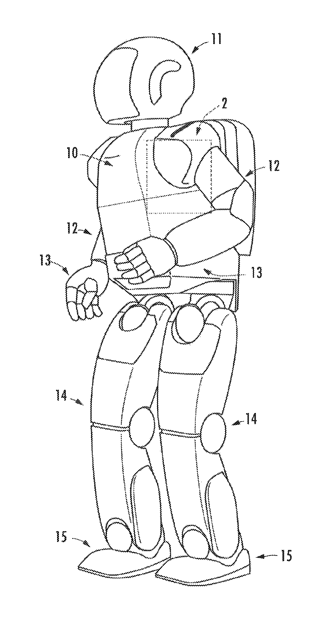
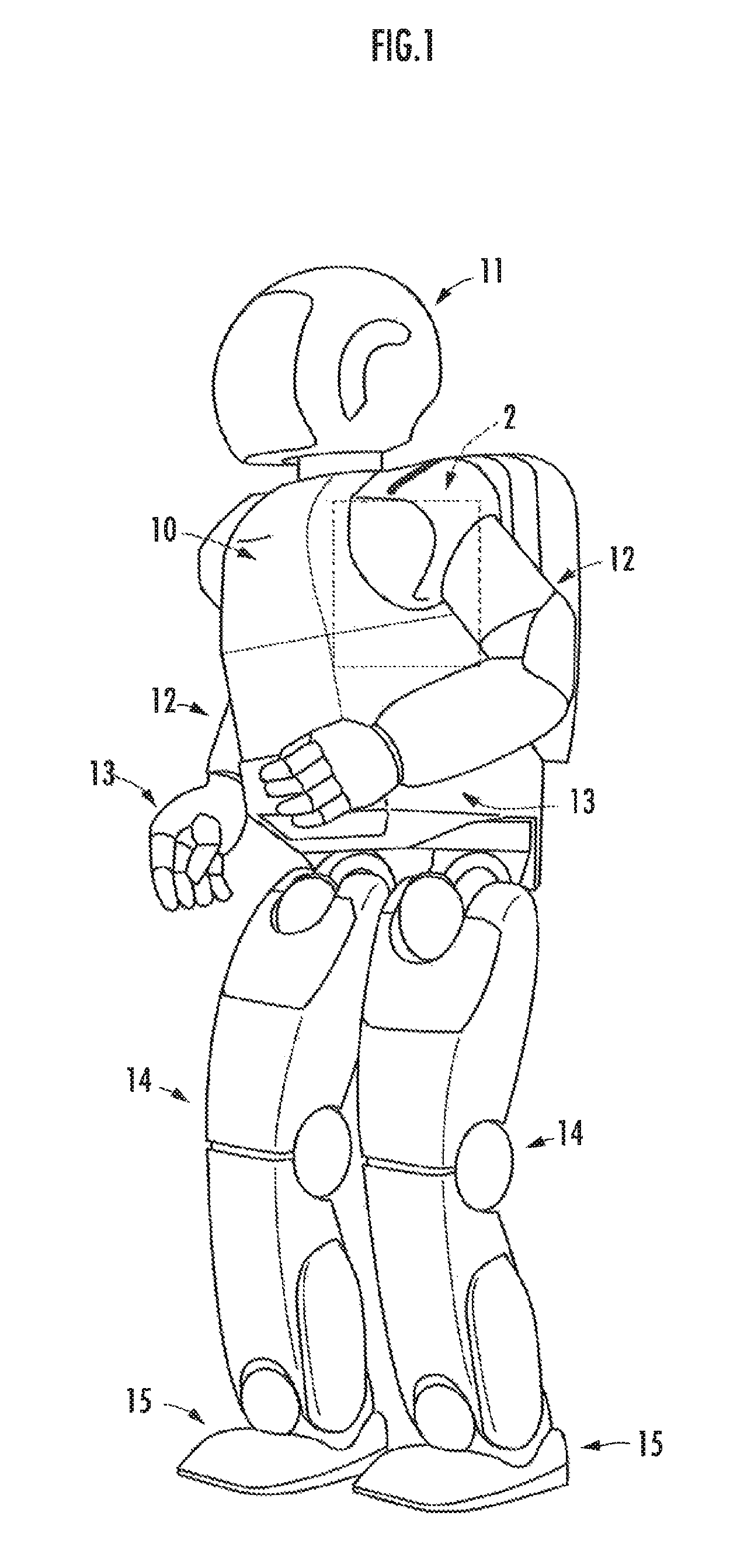
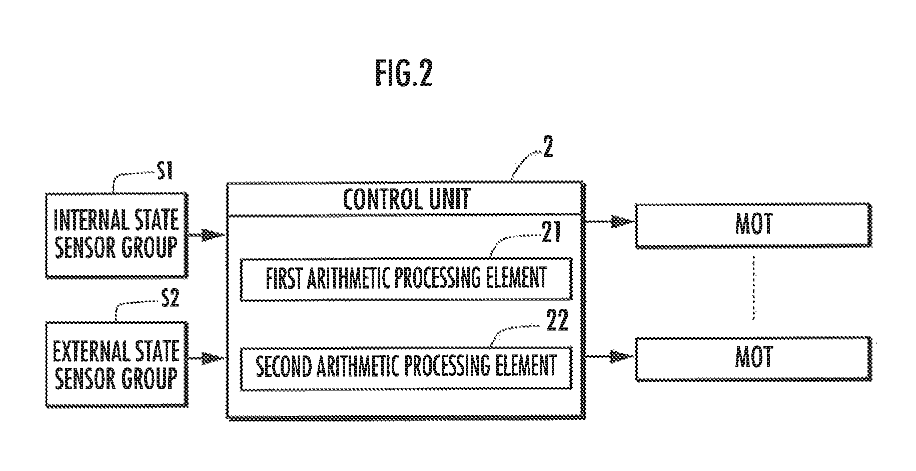
[0024]A robot 1, which is an embodiment of the mobile device in accordance with the present invention illustrated in FIG. 1, is a legged mobile robot. To distinguish between left and right, characters “L” and “R” will be used, as necessary. Like a human being, the robot 1 has a body 10, a head 11 provided on the top portion of the body 10, left and right arms 12 extended from both upper left and right sides of the body 10, hands 13 provided at the distal end portions of the arms 12, left and right legs 14 extended downward from the bottom portion of the body 10, and feet 15 attached to the distal end portions of the legs 14. The robot 1 is capable of bending and stretching the arms 12 and the legs 14, respectively, at a plurality of joint mechanisms corresponding to a plurality of joints, such as shoulder joints, elbow joints, wrist joints, hip joints, knee joints and ankle joints, of a human being by forces transmitted from actuators MOTs (refer to FIG. ...


PUM


Abstract

Provided is a robot capable of achieving more efficient and faster calculation for generating a gait. A target ZMP trajectory of a robot 1 is defined by a linear function of a target landing position that uses a time function as a coefficient. The time function is defined by a function that permits specified function transformation related to time, and a dynamics model is defined by the specified function transformation related to time. Thus, the problem of determining a target landing position is formulated as a problem accompanied by a linear constraint in which a first specified requirement (a target ZMP trajectory linearly approximated by the linear function of a target landing position falls within a permissible existence range) is satisfied.

Description

BACKGROUND OF THE INVENTION[0001]1. Field of the Invention[0002]The present invention relates to the generation of gaits for a legged mobile robot.[0003]2. Description of the Related Art[0004]There has been proposed a technical method whereby to cause a legged mobile robot to act in a pattern that is appropriate in light of a behavior objective of the robot in response to a disturbance of an arbitrary form (refer to Japanese Patent Application Laid-Open No. 2011-031349 and Japanese Patent Application Laid-Open No. 2011-031350).[0005]Specifically, each of a plurality of modules, which are hierarchized according to the frequency band levels, searches for behavior candidates that are the candidates for the behavior patterns of the robot compatible with a main objective and a sub objective while prioritizing the main objective for which a self-module is responsible over the sub objectives for which other modules are responsible. The behavior of the robot is controlled such that a robot ...

Claims


Application Information

Patent Timeline
Patent Type & Authority Patents(United States)
IPC IPC(8): G05B15/00B62D57/032B25J9/10G05B19/00G06F17/18
CPCB25J9/10G06F17/18B62D57/032
Inventor KAMIOKA, TAKUMIKANEKO, HIROYUKI
Owner HONDA MOTOR CO LTD
Why Eureka
Try Eureka