
Optical modeling and calculating method based on Hankel transform and beam propagation method

A calculation method, Hankel's technology, applied in optics, optical components, design optimization/simulation, etc., to achieve high precision, wide application prospects, and shorten the research and development cycle

Active Publication Date: 2021-08-20
FUDAN UNIV
View PDF4 Cites 0 Cited by
  • Summary
  • Abstract
  • Description
  • Claims
  • Application Information

AI Technical Summary

Problems solved by technology

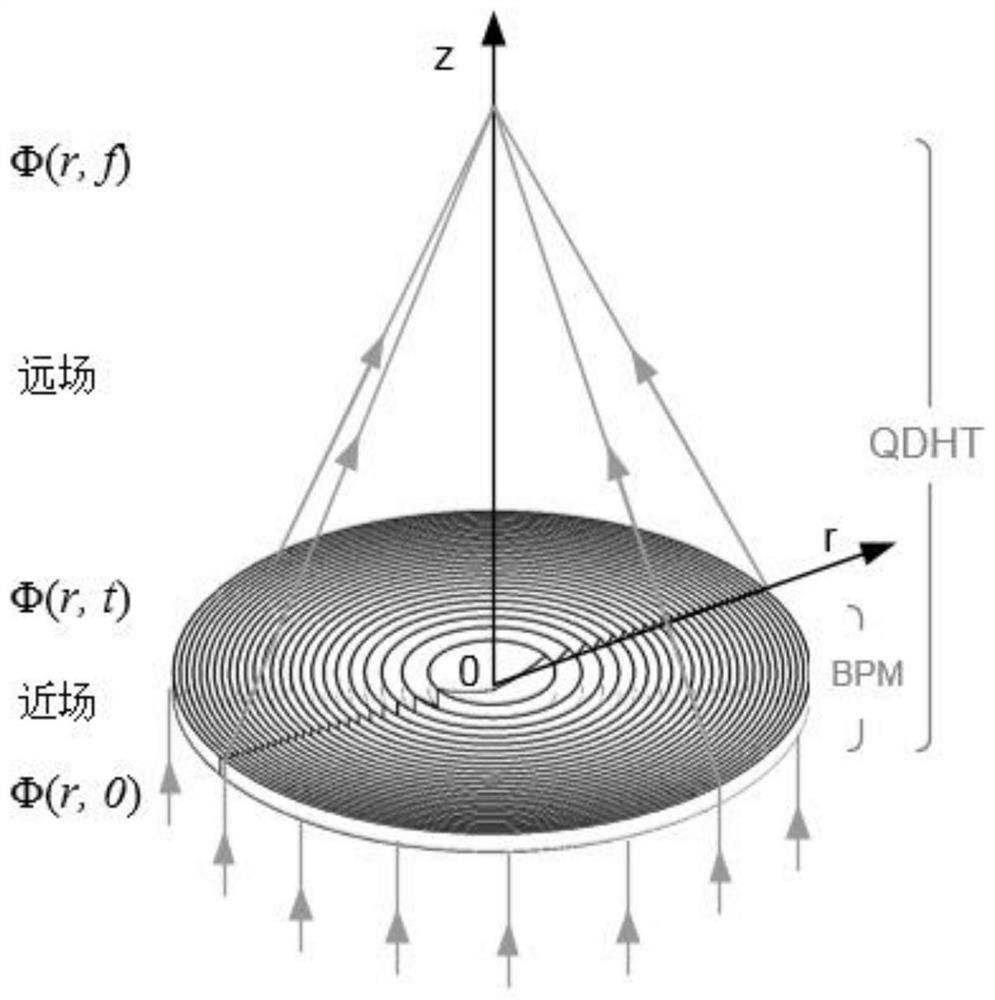
[0004] The purpose of the present invention is to propose an optical modeling and calculation method that can introduce the actual shape of the optical element, high calculation dimension, high precision, and fast calculation speed, so as to solve the problems encountered by other calculation methods mentioned in the above-mentioned background technology

Method used


Image

  • Optical modeling and calculating method based on Hankel transform and beam propagation method
  • Optical modeling and calculating method based on Hankel transform and beam propagation method
  • Optical modeling and calculating method based on Hankel transform and beam propagation method

Examples


Embodiment 1

[0056] Embodiment 1: Calculate the focusing process of the circular HSQ Kinoform optical element with high efficiency focusing under 500eV energy, the specific steps are:

[0057] (1) Set the energy of the incident light field as 500eV, and the plane wave with unit amplitude is incident vertically. The diameter of HSQ Kinoform optical element is 100μm, the thickness is 600nm, the width of the outermost ring is 200nm, the focal length is 4.03mm, the material is silicon dioxide, and the shape is an ideal Kinoform distribution. The cross section along the radial direction is as follows: figure 2 shown.

[0058] (2) The near field of the optical element is calculated by the beam propagation method and the Hankel transformation. The sampling points along the radial direction of the optical element are 2048, the sampling points in the near-field propagation direction are 1024, and the sampling points in the far-field propagation direction are 1024. The distribution of the calcula...

Embodiment 2

[0061] Embodiment 2: Calculate the focusing process of the shape-optimized circular AuKinoform optical element under 8keV energy and its focusing efficiency under different thicknesses. The specific steps are:

[0062] (1) Set the energy of the incident light field as 8000eV, and the plane wave with unit amplitude is incident vertically. The diameter of the AuKinoform optical element is 100μm, the thickness is 2000nm, the width of the outermost ring is 500nm, the focal length is 161mm, the material is gold, and the shape is the optimized Kinoform distribution. The cross section along the radial direction is as follows: Figure 8 shown.

[0063] (2) The near field of the optical element is calculated by the beam propagation method and the Hankel transformation. The sampling points along the radial direction of the optical element are 2048, the sampling points in the near-field propagation direction are 1024, and the sampling points in the far-field propagation direction are 10...

Embodiment 3

[0067] Embodiment 3: Calculate the focusing process of the complex zone plate optical element with shell structure under 5keV energy, the specific steps are:

[0068] (1) Set the energy of the incident light field as 5000eV, and the plane wave with unit amplitude is incident vertically. The diameter of the composite zone plate optical element is 100 μm, the thickness is 2000 nm, the outermost ring width is 500 nm, the focal length is 100.8 mm, and the diameter of the beam stopper is 40 μm. The inner material of the optical element is silicon dioxide, the outer shell material is gold, the thickness is 200nm, and the shape is optimized Kinoform distribution. The cross section along the radial direction is as follows: Figure 14 shown.

[0069] (1) The near field of the optical element is calculated by the beam propagation method and the Hankel transformation. The sampling points along the radial direction of the optical element are 2048, the sampling points in the near-field p...


PUM

PropertyMeasurementUnit
thicknessaaaaaaaaaa
diameteraaaaaaaaaa
thicknessaaaaaaaaaa

Abstract

The invention belongs to the technical field of optical calculation and simulation, and particularly relates to an optical modeling and calculation method based on Hankel transform and a beam propagation method. According to the method, the model of the optical element is created by taking Matlab as a platform, and the method comprises the steps of setting the morphology and the refractive index of the optical element and the wavelength, the amplitude and the waveform of an incident light field. A near-field light field of the rotationally symmetrical optical element is calculated based on a beam propagation method and quasi-discrete Hankel transform, and a light field at any position in a far field is calculated by using a diffraction theory based on quasi-discrete Hankel transform according to an emergent surface light field. According to the method, various optical information modulated by the optical element can be obtained and comprises intensity and phase information of any position in the far field and the near field, so that the transmittance, the focusing efficiency, the focal depth, the focal spot size and the like can be calculated. According to the method, the accuracy and the calculation efficiency of optical simulation are greatly improved, the research and development period can be remarkably shortened in design and optimization of large-aperture and short-wavelength focusing optical elements, and the experiment cost is reduced.

Description

technical field [0001] The invention belongs to the technical field of optical calculation and simulation, in particular to an optical modeling and calculation method based on Hankel transformation and beam propagation method. Background technique [0002] In various imaging systems, optical elements such as focusing and diffraction are crucial components. Among them, optical performance simulation and analysis and calculation are the first and key steps in the design and development of optical components, and play an important guiding role in the design optimization, processing and performance evaluation of optical components. In recent years, with the improvement of the resolution and the complexity of the shape of optical components, the influence of optical phenomena such as diffraction and refraction inside the optical components on the performance of optical components can no longer be ignored. Therefore, traditional calculation methods of geometric optics are no long...

Claims


Application Information

Patent Timeline
Patent Type & Authority Applications(China)
IPC IPC(8): G02B27/00G06F30/20
CPCG02B27/0012G06F30/20
Inventor 童徐杰陈宜方
Owner FUDAN UNIV
Learn More