
Method for determining the height and pipe diameter of internal combustion engine smoke exhaust pipe and internal combustion engine

A technology for smoke exhaust pipes and determination methods, which is applied in the directions of machines/engines, exhaust devices, mechanical equipment, etc., can solve problems such as the unsuitability of exhaust pipes for internal combustion engines, achieve fast and effective calculation, improve calculation accuracy, and reduce chimneys high effect

Active Publication Date: 2016-03-16
CHINA HUADIAN ENG +1
View PDF0 Cites 0 Cited by
  • Summary
  • Abstract
  • Description
  • Claims
  • Application Information

AI Technical Summary

Problems solved by technology

[0003] At present, the calculation of the height of exhaust pipes is mainly for coal-fired power plants. For example, Lan Tao and other scholars published an article in "Environmental Science and Management" in 2011. The height and diameter of the smoke exhaust pipes of coal-fired power plants are designed, but the above method is not applicable to the reasonable size design of the height and diameter of the exhaust pipes of internal combustion engines

Method used


Image

  • Method for determining the height and pipe diameter of internal combustion engine smoke exhaust pipe and internal combustion engine
  • Method for determining the height and pipe diameter of internal combustion engine smoke exhaust pipe and internal combustion engine
  • Method for determining the height and pipe diameter of internal combustion engine smoke exhaust pipe and internal combustion engine

Examples


experiment example 1

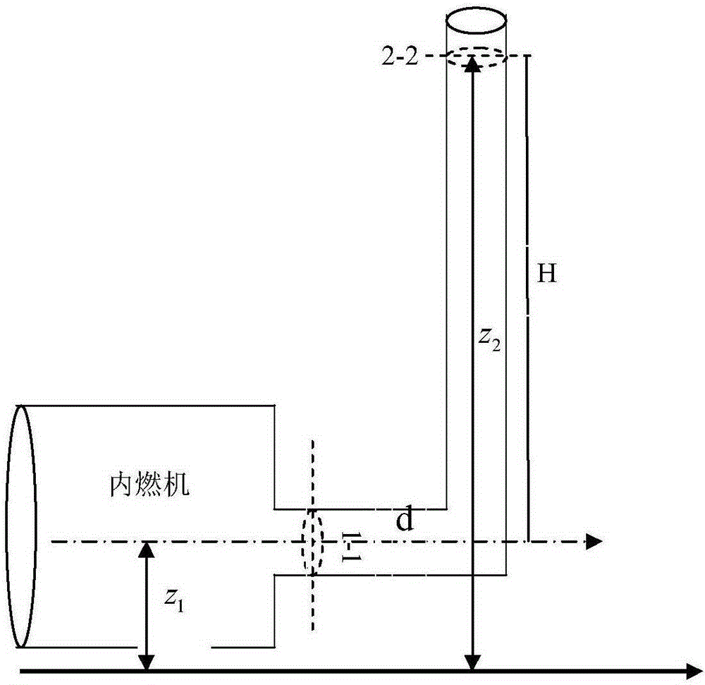
[0059] Experimental example 1: the smoke transmission mode that the present invention adopts sees figure 1 , the flue gas inlet is section 1-1, the flue gas outlet is section 2, the diameter of the exhaust pipe is d, and the height of the exhaust pipe is H.

[0060] The present invention utilizes gas flow rate, flow velocity, smoke exhaust pipe diameter, air leakage coefficient, etc. to reasonably design the size of the height of the internal combustion engine smoke exhaust pipe and the size of the cross-sectional inner diameter, and the steps are as follows:

[0061] 1) The smoke exhaust pipe is based on the steel body material, using the JMS620 internal combustion engine flue flow Q=5.214kg / s provided by the manufacturer to calculate, the diameter of the smoke exhaust pipe is d=900mm, the vacuum degree is not less than 10mm water column, the exhaust pipe exhaust The temperature of the smoke is 160°C; the outlet pressure is 1.01×10 5 Pa;

[0062] 2) From the boiler design m...

experiment example 2

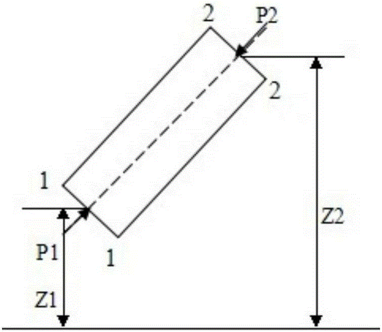
[0066] Experimental example 2: the energy conservation equation of the exhaust pipe among the present invention obtains like this: as figure 2 As shown, columns 1-1 and 2-2 section the Bernoulli equation:

[0067] z 1 + p 1 a b s ρ g + V 1 2 2 g = z 2 + p 2 a b s ρ g + V 2 2 2 g + h w ...


PUM


Abstract

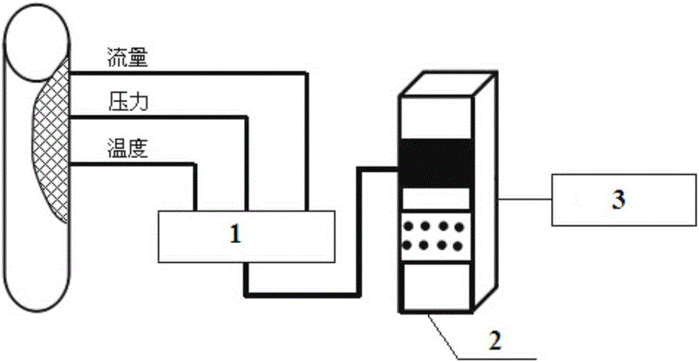
The invention discloses a method of determining the height and diameter of an internal combustion engine smoke exhausting pipe and an internal combustion engine. The method includes steps of 1, measuring the pressure and smoke temperature in the smoke exhausting pipe, and calculating the smoke density of the smoke exhausting pipe inside; 2, measuring the smoke flow in the smoke exhausting pipe, and calculating the smoke flow speed of the smoke exhausting pipe; 3, determining the smoke loss of the smoke exhausting pipe according to the smoke density and smoke flow speed; 4, measuring the air density and the absolute pressures at the inlet section and outlet section of the internal combustion engine smoke exhausting pipe, and acquiring an energy conservation equation of the smoke exhausting pipe according to the air density, the absolute pressure, the smoke density, the smoke flow speed and the smoke loss; 5, determining the height and diameter of sections of the smoke exhausting pipe according to the energy conservation equation of the smoke exhausting pipe. Accurate determination of the height and diameter of the internal combustion engine smoke exhausting pipe can be realized, so that the coordinative benefits of economy and environment are unified.

Description

technical field [0001] The invention relates to a method for determining the height and diameter of a smoke exhaust pipe of an internal combustion engine and an internal combustion engine, belonging to the field of gas distributed energy thermal engineering. Background technique [0002] Gas distributed energy is a new form of clean energy utilization that the country is vigorously developing. This form of energy utilization has a significant effect of energy saving and emission reduction. Since the urban distributed energy station belongs to the building type or the regional type, the gas internal combustion engine is one of the main equipment, and the general rated power is less than 5MW. Among them, the smoke exhaust pipe is one of the important structures in the gas internal combustion engine. The functions of the smoke exhaust pipe are: first, to generate self-generated draft to overcome the resistance of smoke and air duct; second, to lead the exhaust gas generated by ...

Claims


Application Information

Patent Timeline
Patent Type & Authority Patents(China)
IPC IPC(8): F01N13/08
Inventor 李和平邱兆国
Owner CHINA HUADIAN ENG
Learn More