Planetary gear stage with plain bearings as planet bearings and use thereof

a technology of planet gears and planet gears, which is applied in the direction of sliding contact bearings, gearboxes, machines/engines, etc., can solve the problems of increasing the possibility of deformation during operation of wind turbines, disadvantageous bearing arrangements of planet gears, and increasing the possibility of deformation of planet gears as described above, so as to facilitate deformation and less wear.

Active Publication Date: 2016-08-16
HANSEN TRANSMISSIONS
View PDF20 Cites 15 Cited by
  • Summary
  • Abstract
  • Description
  • Claims
  • Application Information

AI Technical Summary

Benefits of technology

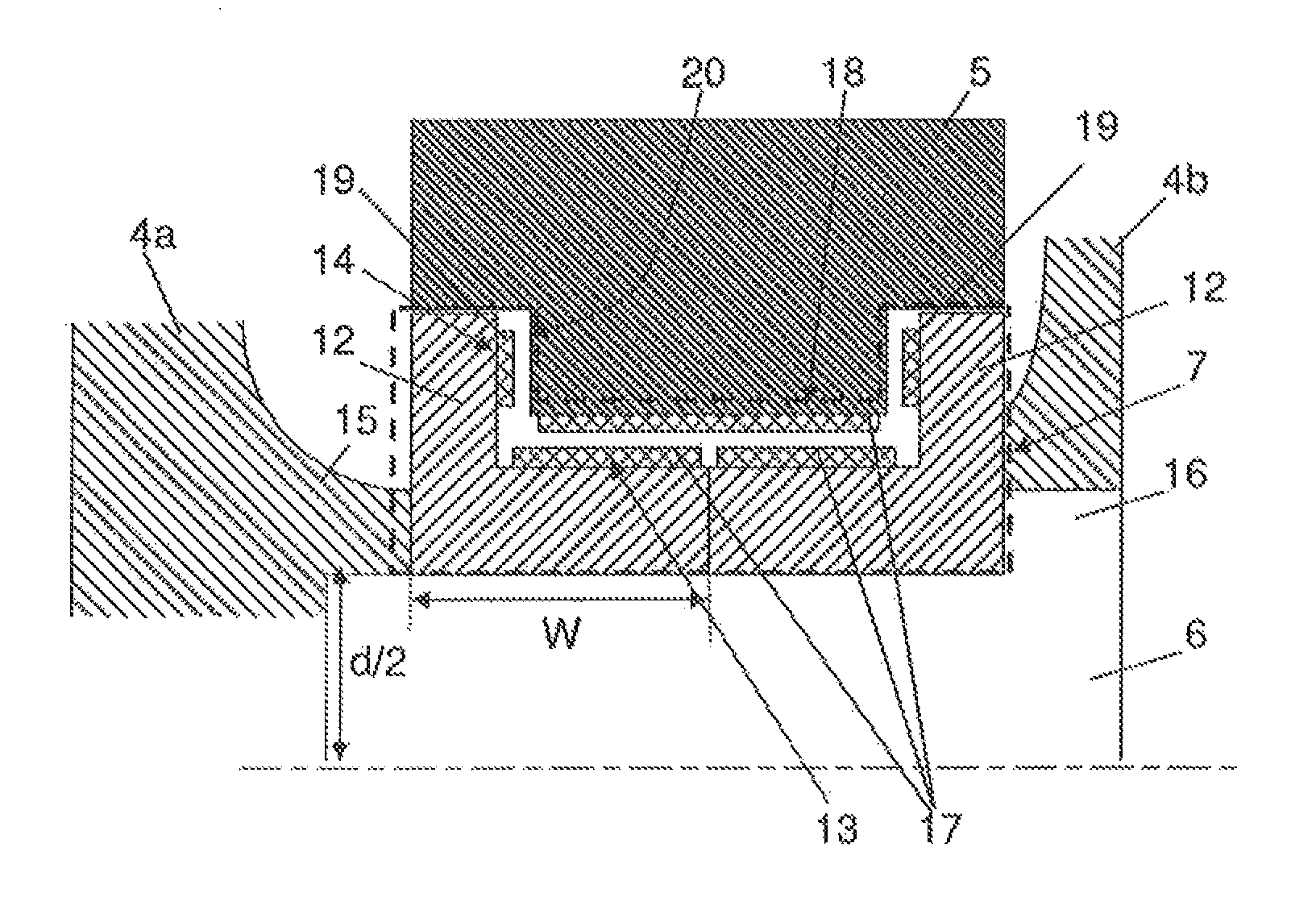
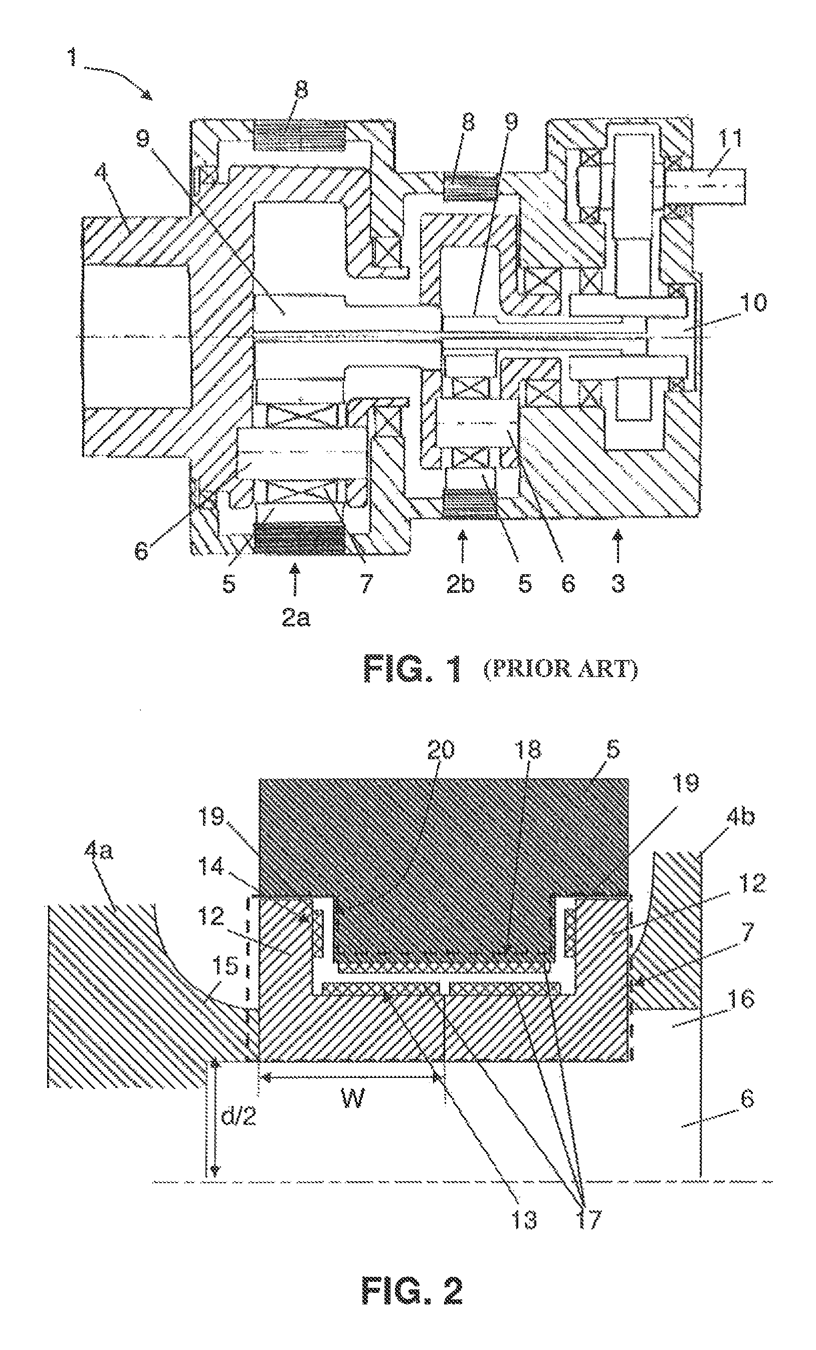
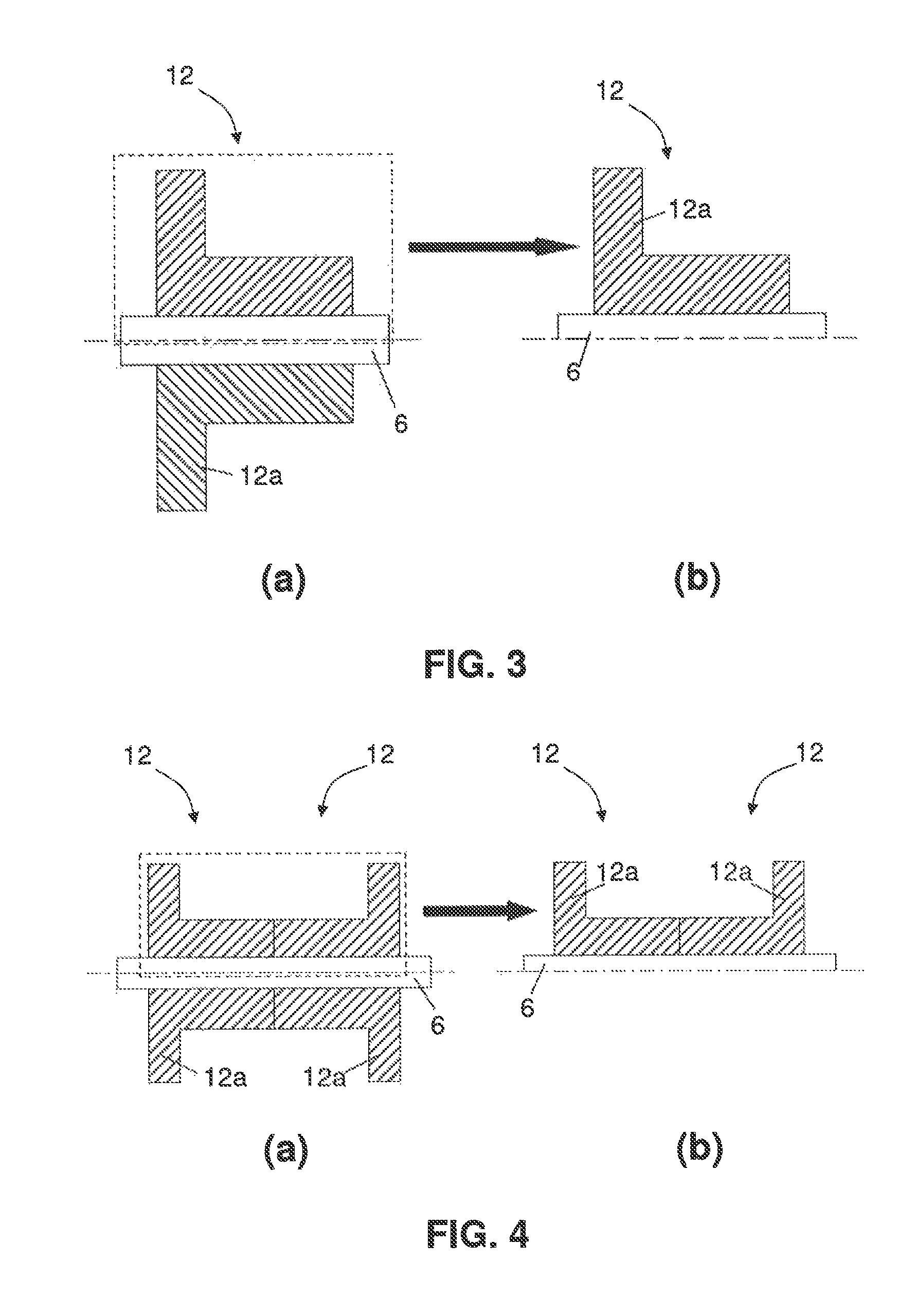
[0011]Furthermore, in a planetary gear stage according to embodiments of the present invention, the plain bearing arrangement can be used with any size of planet gears, because the L-shaped bushings can easily be adapted in size at their sides which are to be connected so as to form the U-shape, e.g. by grinding, or a spacer or a further bushing can be placed in between the L-shaped bushings.
[0012]Moreover, because the plain bearing arrangement comprises two L-shaped bushings, it can more easily adapt to deformations of the planet gear which may occur during operation of the gearbox in which the planetary gear stage is mounted, which leads to less wear and thus to a longer life time of the plain bearing arrangement.

Problems solved by technology

The increasing demand for multi-megawatt wind turbines puts a challenging pressure on new designs of components such as gearboxes for such wind turbines.
This flexibility may increase the possibility of deformation during operation of the wind turbine.
Furthermore, when using plain bearings for supporting planet gears, deformations of the planet gears as described above may be disadvantageous for these bearing arrangements.
The plain bearing may wear-out locally, which may reduce its effectiveness and may even lead to failure of the bearing.

Method used


Image

  • Planetary gear stage with plain bearings as planet bearings and use thereof
  • Planetary gear stage with plain bearings as planet bearings and use thereof
  • Planetary gear stage with plain bearings as planet bearings and use thereof

Examples


Embodiment Construction

[0034]In the description different embodiments will be used to describe the invention. Therefore reference will be made to different drawings. It has to be understood that these drawings are intended to be non-limiting, the invention is only limited by the claims. The drawings are thus for illustrative purposes, the size of some of the elements in the drawings may be exaggerated for clarity purposes.

[0035]The term “comprising” is not to be interpreted as limiting the invention in any way. The term “comprising”, used in the claims, is not intended to be restricted to what means is described thereafter; it does not exclude other elements, parts or steps.

[0036]The term “connected” as used in the claims and in the description is not to be interpreted as being restricted to direct connections, unless otherwise specified. Thus, part A being connected to part B is not limited to part A being in direct contact to part B, but also includes indirect contact between part A and part B, in other...


PUM


Abstract

A planetary gear stage for a gearbox has a ring gear, a sun gear and a planet carrier for driving planet shafts. Each planet shaft has a planet gear with radial and axial contact surfaces and which is rotatably supported by a plain bearing arrangement. The bearing arrangement has two bushings fixed to the planet shaft. Each bushing is L-shaped in cross-section and has radial and axial contact surfaces. The bushings form a cross-sectional U-shape and are axially locked by abutments. At least part of the planet gear is located within the U-shape formed by the bushings. The plain bearing arrangement has a radial sliding support arranged between the radial contact surface of the bushings and the radial contact surface of the planet gear and an axial sliding support arranged between the axial contact surface of the bushings and the axial contact surface of the planet gears.

Description

[0001]This application is a National Stage completion of PCT / EP2013 / 057345 filed Apr. 9, 2013, which claims priority from European patent application serial no. 12167088.9 filed May 8, 2012.FIELD OF THE INVENTION[0002]The present invention relates to a planetary gear stage for a gearbox for a wind turbine. More particular, the present invention relates to a planetary gear stage comprising plain bearings for rotatably supporting planet gears in the planetary gear stage.BACKGROUND OF THE INVENTION[0003]The wind turbine market is changing fast nowadays. There is a continuing demand for larger wind turbines being able to generate a higher number of megawatts of electricity, also referred to as multi-megawatt wind turbines. At the same time the requirements for reduction of size and weight of the turbines and their components become more and more important.[0004]In wind turbines, typically a wind turbine rotor drives a low speed shaft of a gear transmission unit or gearbox, which transfo...

Claims


Application Information

Patent Timeline
Patent Type & Authority Patents(United States)
IPC IPC(8): F16H57/08F16C17/26F16C33/12F16C17/18F16C17/10
CPCF16C17/107F16C17/18F16C17/26F16C33/122F16H57/082F16C17/105F03D15/00F16H2057/085F16C2361/61F16C2360/31F03D80/70F03D15/10Y02E10/72F16H37/041
Inventor VAN DEN DONKER, MICHIELBOGAERT, ROGERLEIMANN, DIRK
Owner HANSEN TRANSMISSIONS
Why Eureka
Try Eureka