Method and system for network micro flow control

a network micro and flow control technology, applied in the field of network micro flow control, can solve the problems of reducing the buffering needs of switching fabrics, reducing the number of dropped data packets, and inefficient conventional flow control techniques,

Active Publication Date: 2016-08-16
GOOGLE LLC
View PDF13 Cites 26 Cited by
  • Summary
  • Abstract
  • Description
  • Claims
  • Application Information

AI Technical Summary

Benefits of technology

[0005]The present technology pertains to unilaterally patterning and transmitting individual data packets over a network without the need to receive feedback from any of the network's components or from the network itself. More particularly, the present technology relates to a sending device preemptively interleaving the individual data packets in specific patterns and consecutively transmitting them together to multiple target receivers to reduce buffering needs in switching fabrics. By doing so, the sending device reduces buffering needs in switching fabrics and also reduces the number of dropped data packets.
[0008]In another example, the method further comprises applying an outbound limit to the first transmission sequence pattern, the outbound limit reducing a rate of transmission of the interleaved data packets of the first transmission sequence pattern, whereby transmission of the interleaved data packets in the first time block according to the outbound limit elongates a length of time of the first time block. Moreover, the rate of transmission is reduced in half.
[0010]In a further example, the method further comprises defining an inbound limit associated with the data packet congestion at a buffer of the respective receiver, the inbound limit reducing a rate of transmission of the interleaved data packets of the second transmission sequence pattern, whereby transmission of the interleaved data packets of the second transmission sequence pattern according to the inbound limit elongate a length of time of the second time block.
[0015]In another example, the system is configured to define an inbound limit associated with data packet congestion at a buffer of the respective receiver, the inbound limit reduces a rate of transmission of the interleaved data packets of the first transmission sequence pattern, whereby transmission of the interleaved data packets of the first transmission sequence pattern according to the inbound limit which elongates a length of time of the first time block. The network interface device is further configured to interleave one or more data packets associated with a third message in between one or more time gaps of the elongated length of time of the first time block; and the transmitter module is further configured to transmit the one or more data packets associated with the third message consecutively together in the elongated first time block.
[0016]In yet another example, the system is further configured to define an inbound limit associated with the data packet congestion at a buffer of the respective receiver, the inbound limit reduces a rate of transmission of the interleaved data packets of the second transmission sequence pattern according to the inbound limit which elongates a length of time of the second time block.

Problems solved by technology

Unfortunately, many conventional flow control techniques are inefficient and prone to transmission errors.
For instance, if there are multi-packet messages simultaneously pending to be sent to a plurality of machines at various switches, an ACK or a PAUSE frame received from just one switch may significantly delay and back-up the transmission of all the messages.
This results in undesirable time delay in message transmissions.
Furthermore, the probability of a network switch dropping data packets increases when it attempts to receive long bursts of packets from multiple senders at approximately the same time.

Method used


Image

  • Method and system for network micro flow control
  • Method and system for network micro flow control
  • Method and system for network micro flow control

Examples


Embodiment Construction

[0028]The aspects, features and advantages of the present technology will be appreciated when considered with reference to the following description of preferred embodiments and accompanying figures. The same reference numbers in different drawings may identify the same or similar elements. Furthermore, the following description does not limit the disclosure; rather, the scope of the technology is defined by the appended claims and equivalents.

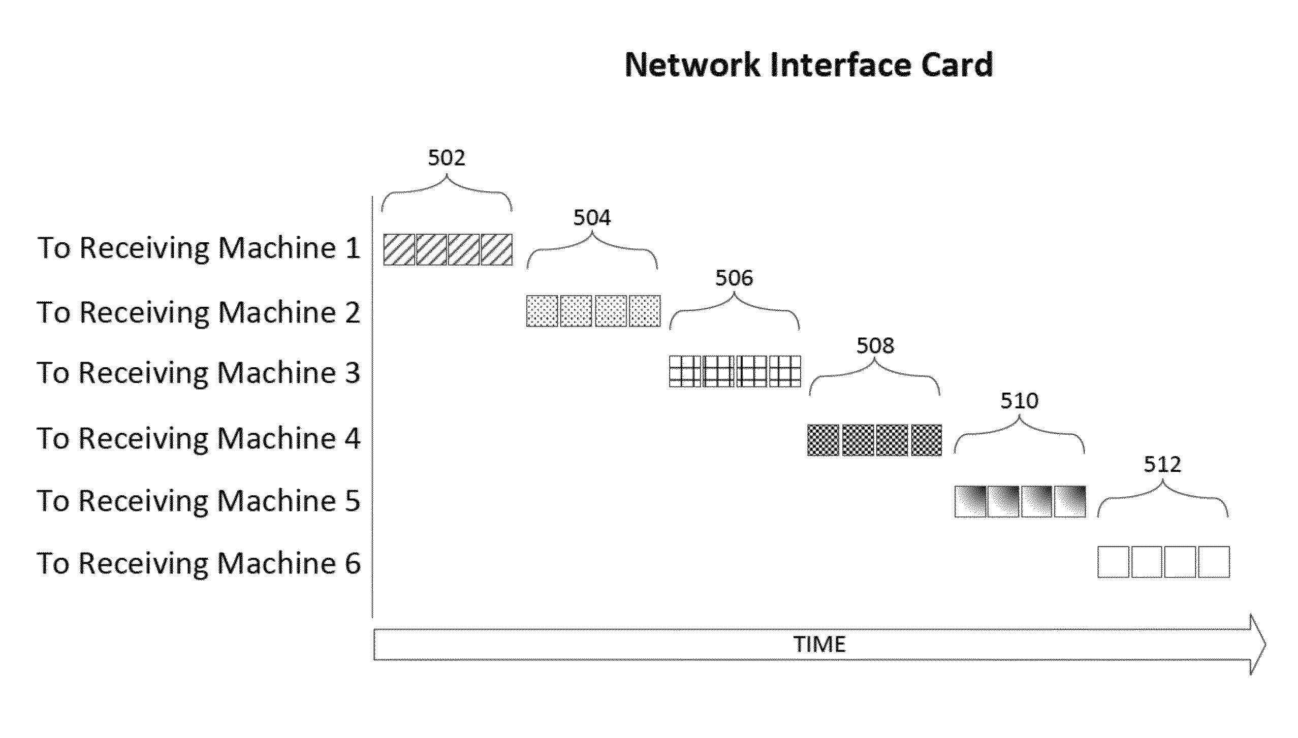
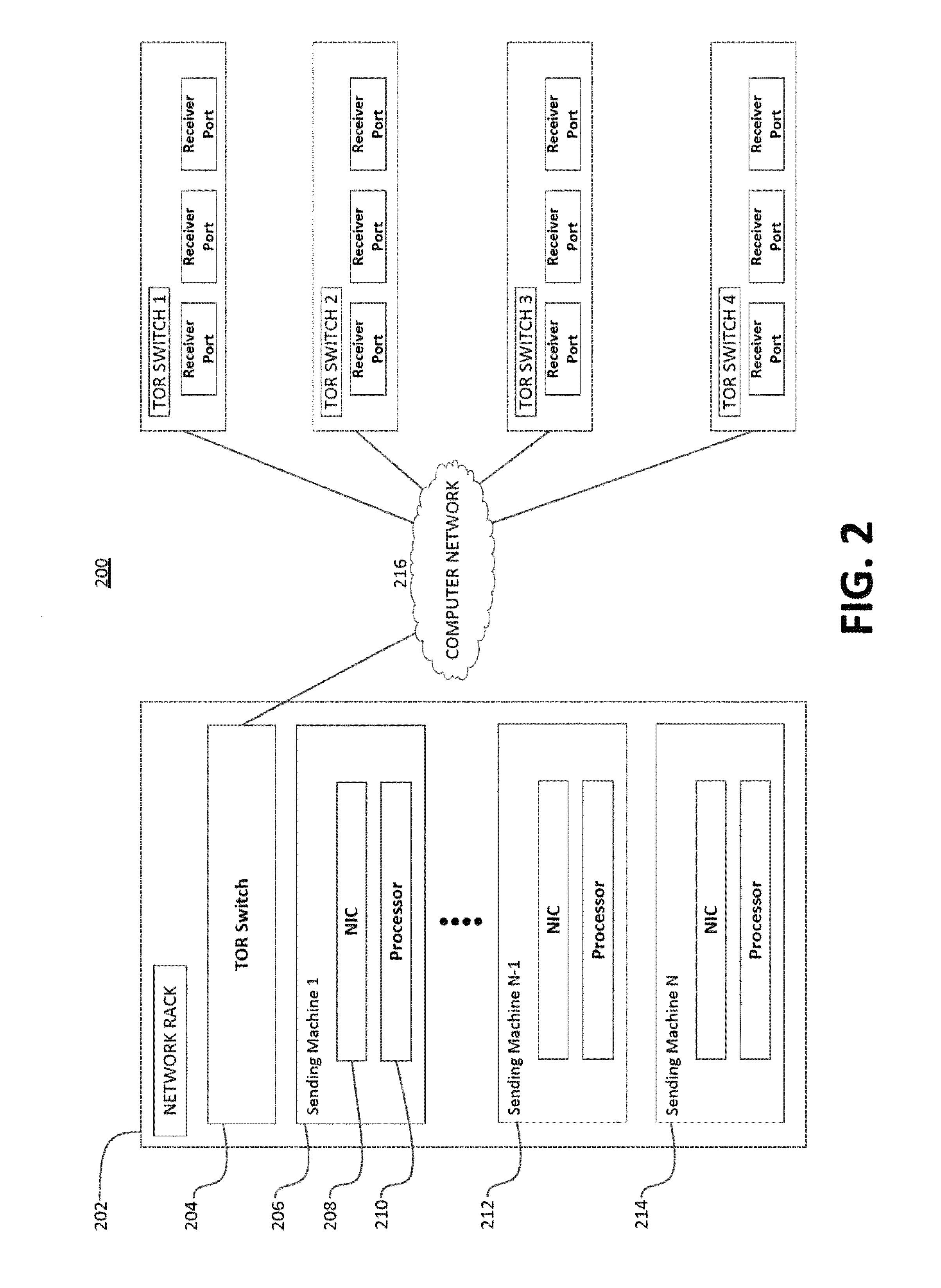
[0029]In accordance with aspects of the present technology, a network transmitter has at least one multi-packet message pending to be sent to one or more receiving machines. As will be explained in more detail below, the network transmitter may be implemented on a network interface controller (“NIC”) or software running on a processor. In addition, the present technology may also be applied to each priority or Quality of Service (“QoS”) level.

[0030]Systems and methods are used to preemptively interleave individual data packets in specific patt...


PUM


Abstract

The present technology pertains to unilaterally interleaving individual data packets of long bursts of multi-packet messages in various sequence patterns to be sent to one or more receivers over a network. Before determining a pattern, the sending device attempts to reduce the transmission length of the long bursts of the data packets into multiple chunks. Subsequently, the sending device generates a sequence pattern of the individual data packets and consecutively transmits these packets to their respective receivers. The determined sequence pattern may be based upon outbound limits at the sender, inbound limits at the one or more receivers, and various transmission priorities. Moreover, the sender may limit the data flow of any message transmission. The present technology does not require feedback from the network's components or from the network itself to micro flow control the individual data packets.

Description

BACKGROUND[0001]The booming growth of network communication (e.g., Ethernet, Wi-Fi, Token Ring) and the need to decrease message frames from dropping at various points during network congestion has prompted the use of data flow control techniques. At a high level, the concept of data flow control is the process of overseeing and managing the rate of data transmission between various nodes of a network. For instance, if the rate of data transmission from a sending node is faster than the rate at which a receiving node can handle, then the device (e.g., switch) at the receiving node will send a signal to the sending node to temporarily stop transmission until it can catch up to speed.[0002]A simple example of flow control is the stop-and-wait technique. In this particular example, the message to be transmitted is broken down into multiple frames. The receiver indicates that it is ready to receive data for each frame. The sender then sends the first frame. Meanwhile, the sender waits a...

Claims


Application Information

Patent Timeline
Patent Type & Authority Patents(United States)
IPC IPC(8): H04L12/16H04L12/801
CPCH04L47/18H04L47/122H04L47/25H04L47/34
Inventor SITES, RICHARD LEE
Owner GOOGLE LLC
Why Eureka
Try Eureka