Electric vehicle and thermal management system therefor

a technology of thermal management system and electric vehicle, which is applied in the direction of refrigeration components, transportation and packaging, light and heating equipment, etc., can solve the problems of reduced travel distance of the vehicle, low heating efficiency, and difficulty in satisfying the heating requirement, so as to reduce the charging amount of refrigerant, improve the effect of cooling the heat generating components and the comfort of the compartment, and reduce the heat waste

Active Publication Date: 2016-08-30
HANGZHOU SANHUA RES INST CO LTD
View PDF26 Cites 3 Cited by
  • Summary
  • Abstract
  • Description
  • Claims
  • Application Information

AI Technical Summary

Benefits of technology

[0008]An object of the present application is to provide a thermal management system, which is able to ensure the sufficient use of the heat of the heat generating components of the electric vehicle, thus reducing the heat waste, meanwhile improving the effect of cooling the heat generating components and the comfort of the compartment, reducing the charging amount of the refrigerant, preventing the refrigerant from entering into the compartment. Another object of the present application is to provide an electric vehicle including the above thermal management system.
[0027]In operation, the refrigerant flows at high temperature and high pressure through the condenser under the action of the compressor, and transfers heat to the medium within the heat dissipating device via the condenser, raising the temperature of the medium within the heat dissipating device. Then, the refrigerant preliminarily cooled flows through the throttling element, achieving the further cooling of the refrigerant by changing the state of the refrigerant. Then, the refrigerant with lower temperature flows through the evaporator, absorbing the heat of the medium within the heat recovery cooling device, and thus reducing the temperature of the medium within the heat recovery cooling device. The refrigerant that has absorbed heat is brought into the next circulation under the action of the compressor, and continuously transfers the heat of the heat recovery cooling device to the heat dissipating device. The medium in the heat recovery cooling device proportionally flows through the heat exchanger for heat generating components and the cooler under the regulating action of the second flow regulating valve. The medium passing through the heat exchanger for heat generating components absorbs the heat of the heat generating components, so as to achieve the purpose of cooling the heat generating components, while the medium passing through the cooler absorbs the heat of the medium in the compartment temperature adjusting device, so as to achieve the purpose of cooling the medium in the compartment temperature adjusting device. The medium in the heat recovery cooling device that has absorbed heat brings the heat to the evaporator, and transfers the heat to the refrigerant in the refrigerating device. Besides, the connection state of the second air-cooled heat exchanger of the heat recovery cooling device is changed according to the temperature of the external surroundings such that the second air-cooled heat exchanger is in a working state or a non-working state. When the second air-cooled heat exchanger is in a working state, the medium in the second air-cooled heat exchanger can absorb the heat in the air or release heat into the air according to the temperature of outside air and the temperature of the medium, so as to assist in heat absorption or heat radiation. The medium in the heat dissipating device proportionally flows through the first air-cooled heat exchanger and the heater under the regulating action of the first flow regulating valve. The medium flowing through the first air-cooled heat exchanger dissipates heat to the air, so as to reduce the temperature of the medium, while the medium flowing through the heater heats the medium of the compartment temperature adjusting device. As a result, under the combined action of the heater and the cooler, the compartment temperature adjusting device reaches the required temperature, thus achieving the adjustment of the compartment temperature and satisfying the requirement of the comfort of the compartment.
[0028]It can be seen that the thermal management system for the electric vehicle according to the present application uses the medium in the heat recovery cooling device to absorb the heat of the heat generating components and / or the heat of the medium in the compartment temperature adjusting device, and the heat is transferred to the refrigerant within the refrigerating device by the evaporator, thereby achieving the purpose of cooling the heat generating components and the medium of the compartment temperature adjusting device. The cooling of the heat generating components ensures the normal operation of the heat generating components, and the cooling of the medium of the compartment temperature adjusting device preliminarily prepares for the adjustment of the compartment temperature. Under the action of the compressor, the refrigerant that has absorbed heat flows through the condenser, so that the heat is transferred to the medium of the heat dissipating device via the condenser; and then, the medium within the heat dissipating device flows through the first air-cooled heat exchanger and / or the heater, so that the heat is dissipated into the air via the first air-cooled heat exchanger, or is used to heat the medium of the compartment temperature adjusting device. In this way, the medium can meet the temperature requirement, and finally allow the compartment to be at the required temperature. Thus, the thermal management system according to the present application transfers the heat of the heat generating components into the compartment, thereby achieving the cooling of the heat generating components and the adjustment of the compartment temperature. As such, the heat within the electric vehicle may be utilized reasonably, that is, relatively few devices and relatively simple connecting circuit are used to achieve the reasonable heat transfer, improve the utilization factor of the heat, and comprehensively solve the problems existing in the heat dissipation of the heat generating components, in the temperature control of the compartment and in the reasonable use of the heat, thereby achieving the overall management of the thermal system of the electric vehicle. On the other hand, various devices can select different mediums, so the new environmentally friendly refrigerant (such as R1234yf and R152a and the like) can be used in the refrigerating device, thereby reducing the charging amount of the flammable refrigerant; further, the refrigerating device containing flammable refrigerant can be provided outside the compartment, so as to completely avoid the refrigerant from entering the compartment, thereby improving the security.

Problems solved by technology

However, the power of the electric vehicle mainly comes from the electric motor, and the temperature of the circulating cooling water of the electric vehicle is only 50 degrees since the heat of the engine may not be used, which has difficulty in satisfying the heating requirement.
However, among the various heating ways described above, if the independent heat source, such as PTC, is adopted to heat, a lot of battery energy will be consumed, resulting in a reduced travel distance of the vehicle; if fuels are used to heat, not only low heating efficiency but also environmental pollution may occur, and the load of the vehicle may be increased.
In this way, the heat is not better used, and the heat generating components are poorly cooled under a high ambient temperature, and cannot work at the optimum temperature.
Such refrigerant is expensive and flammable, which may become problems existing in the present thermal system of the electric vehicle.

Method used


Image

  • Electric vehicle and thermal management system therefor
  • Electric vehicle and thermal management system therefor
  • Electric vehicle and thermal management system therefor

Examples


first embodiment

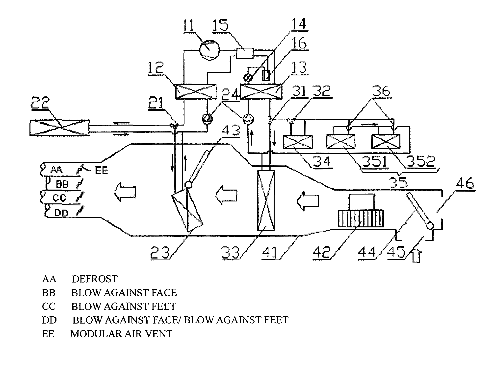
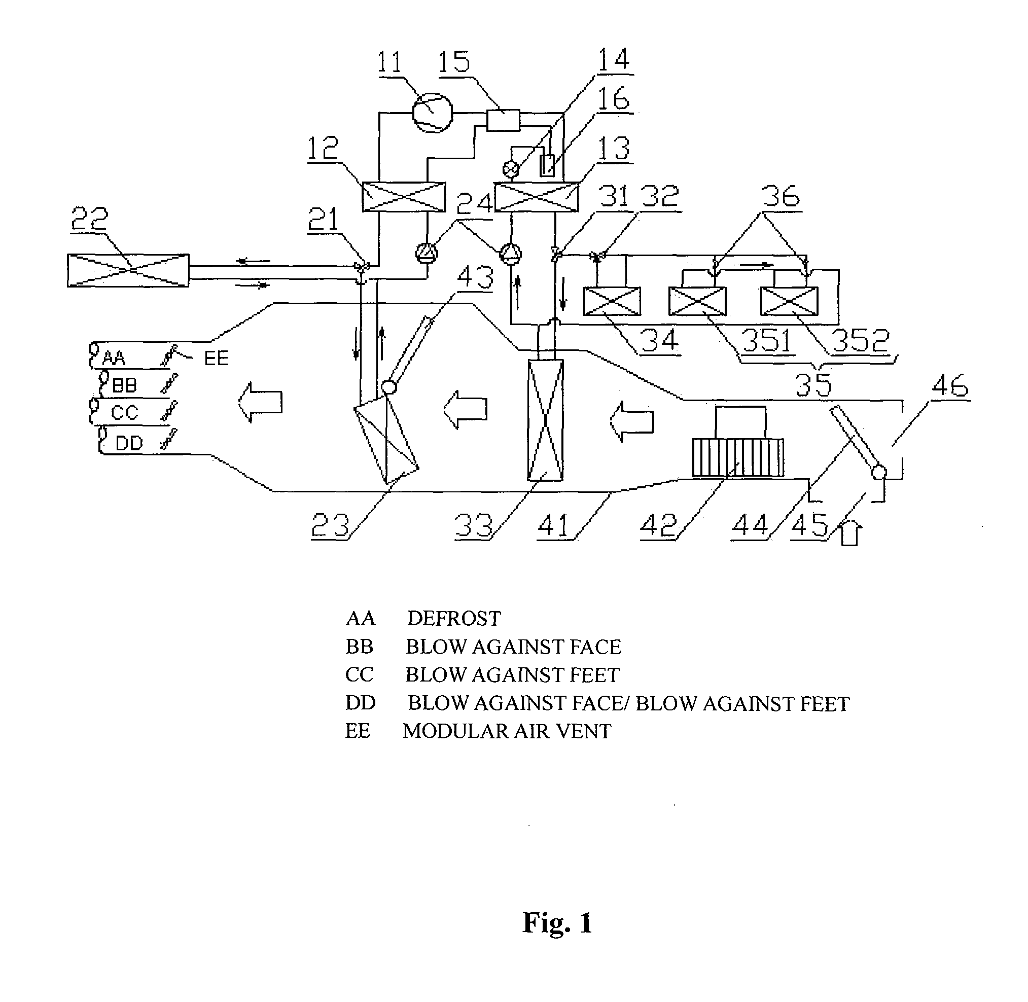
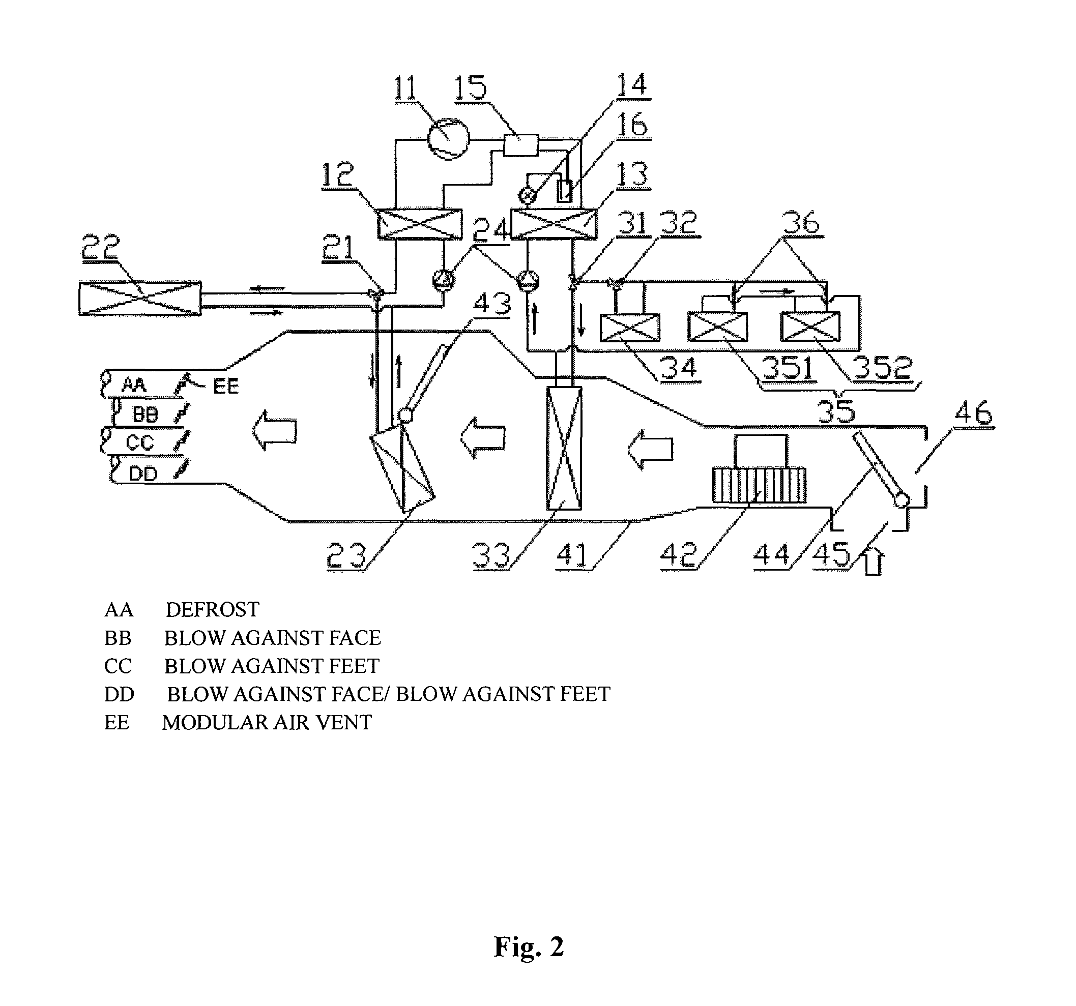
[0035]Referring to FIGS. 1 and 2, FIG. 1 is a schematic structural view of a thermal management system in a first working mode according to the present application; and FIG. 2 is a schematic structural view of the thermal management system shown in FIG. 1 in a second working mode.

[0036]In the first embodiment, the thermal management system for the electric vehicle according to the present application includes a heat recovery cooling device, a refrigerating device, a heat exchanging device or heat exchanging circuit and a compartment temperature adjusting device. The refrigerating device includes a compressor 11, a condenser 12, a throttling element 14 and an evaporator 13 that are connected with each other by pipelines. The heat exchanging device includes a first air-cooled heat exchanger 22 and a heater 23 that are connected by pipelines. The heat recovery cooling device includes a heat exchanger 35 for heat generating components, a second air-cooled heat exchanger 34 and a cooler ...

second embodiment

[0051]Referring to FIG. 3, it is a schematic structural view of a thermal management system in the first working mode according to the present application.

[0052]Of course, in another specific embodiment, the compartment temperature adjusting device is a medium circulating device. The medium circulating device includes a heat exchanger 41′ within the compartment. The cooler 33, the heater 23 and the heat exchanger 41′ within the compartment are connected in series by pipelines. If the power pump 24 is also provided in the circulation circuit of the device, under the action of the power pump 24, the medium flows through the cooler 33 and the heater 23 to reach the heat exchanger 41′ within the compartment. A heat exchange occurs between the medium and the air in the compartment, thereby achieving the adjustment of the compartment temperature. The position of the cooler 33 and the heater 23 can be adjusted arbitrarily to facilitate the arrangement of other devices. Furthermore, the hea...


PUM


Abstract

A thermal management system includes a cooling circuit, a heat exchange circuit, a heat recovery cooling device and a passenger compartment temperature regulating device. The cooling device includes a condenser, a throttling element and an evaporator. The heat exchange device includes a first air cooled heat exchanger and a heater. The heat recovery cooling device includes a pump, a second air cooled beat exchanger and a cooler. The passenger compartment temperature regulating device includes an air flowing passage and a fan arranged in the air flowing passage, or a compartment heat exchanger. The first air cooled heat exchanger and the heater are in communication with the condenser through a first flow regulating valve. The cooler and the heat emission component heat exchanger are in communication with the evaporator through a second flow regulating valve. The second air cooled heat exchanger is selectively connected in series to the heat emission component heat exchanger.

Description

[0001]The present application claims the benefit of priority of Chinese Patent Application No. 201010526741.5, entitled “ELECTRIC VEHICLE AND THERMAL MANAGEMENT SYSTEM THEREFOR”, filed with the Chinese State Intellectual Property Office on Oct. 29, 2010, the entire disclosure of which is incorporated herein by reference.FIELD OF THE INVENTION[0002]The present application relates to the technical field of distribution and use of heat, and particularly to a thermal management system. The present application also relates to an electric vehicle including the thermal management system.BACKGROUND OF THE INVENTION[0003]The electric vehicle will become the trend of development of vehicles in the future due to characteristics of energy saving and environmental protection.[0004]With the development of the vehicle, more and more attention has been paid to comfort inside a compartment. For the conventional vehicle with an internal combustion engine, the residual heat of the internal combustion ...

Claims


Application Information

Patent Timeline
Patent Type & Authority Patents(United States)
IPC IPC(8): B60H1/00B60H1/22B60H1/32B60H1/14
CPCB60H1/00278B60H1/00899B60H1/00057B60H1/22B60H1/3204B60H1/00392B60H1/143B60H1/0005B60H1/323B60H2001/00307B60H1/00007B60H2001/00957B60H2001/3288B60H2001/3289B60H1/32284
Inventor ZHANG, RONGRONGSHI, CHULIANG
Owner HANGZHOU SANHUA RES INST CO LTD
Why Eureka
Try Eureka