Landscape safety apparatus, associated combinations, methods, and kits

Inactive Publication Date: 2016-09-06
LANDSCAPE SAFETY SYST
View PDF4 Cites 9 Cited by
  • Summary
  • Abstract
  • Description
  • Claims
  • Application Information

AI Technical Summary

Benefits of technology

[0019]A housing may be associated with the first support and/or retraction mechanism. For example, the housing may be integral to the first support. In addition, the housing may have a size effective to contain the entire screen upon retraction. Furthermore, a plurality of handles may be provided. For example, a first handle may be attached to the retraction mechanism, a second handle may be attached to the housing, and a third handle may be attached to the screen and/or the second support.
[0020]In another embodiment, a landscaping method is provided. The method involves identifying a grounds region for using a landscaping device powered by an engine and/or motor capable of hurling debris during operation up to a height of at least about 18 inches. A shield apparatus is transported to the region. The shield apparatus comprises first and second supports, each support having an upper end and a lower end, first and second bases each having a rod insertable up to a bulge into the lower ends of the first and second supports, respectively, the bases having a construction to maintain the supports in a substantially vertical orientation above the bulges, a flexible screen having opposing hems attached to the first and second supports, the screen having sufficient strength to block debris hurled by the device from traveling through the screen, and a retraction mechanism associated with the first support, the retraction mechanism having a construction such that the second support may be automatically locked relative to and automatically pulled toward the first support, as desired. The rods of the first and second bases are inserted into the lower ends of the first and second supports. The first and second supports are positioned in a substantially vertical orientation at different locations bounding the region while automatically locking the

Problems solved by technology

Riding lawnmowers and garden tractors, alone, account for the injury and/or death of tens of thousands individuals each year.
In addition, landscaping injuries can arise through a number of other routes as well.
There are no OSHA standards for protecting passersby and bystanders.
As with any power tool such as mowers, blowers, and rototillers, string trimmers are capable of causing injury if not used in a safe manner.
Improper operation of string trimmers is hazardous because the rotating cutting string is exposed.
The exposed cutting string has been known to occasionally hit the leg of the operator of the trimmer, thus causing injury to the operator's leg.
While these guards may, to some extent, prevent a user from inadvertently causing the rotating string from coming into contact with legs or feet of the user, these guards do little to prevent cuttings from being thrown toward the bystanders and passersby.
Known string-trimmer guards and debris barriers suffer from a number of drawbacks not addressed by prior art technologies.
Furthermore, while prior art technologies generally focus on prote

Method used


Image

  • Landscape safety apparatus, associated combinations, methods, and kits
  • Landscape safety apparatus, associated combinations, methods, and kits
  • Landscape safety apparatus, associated combinations, methods, and kits

Examples


Embodiment Construction

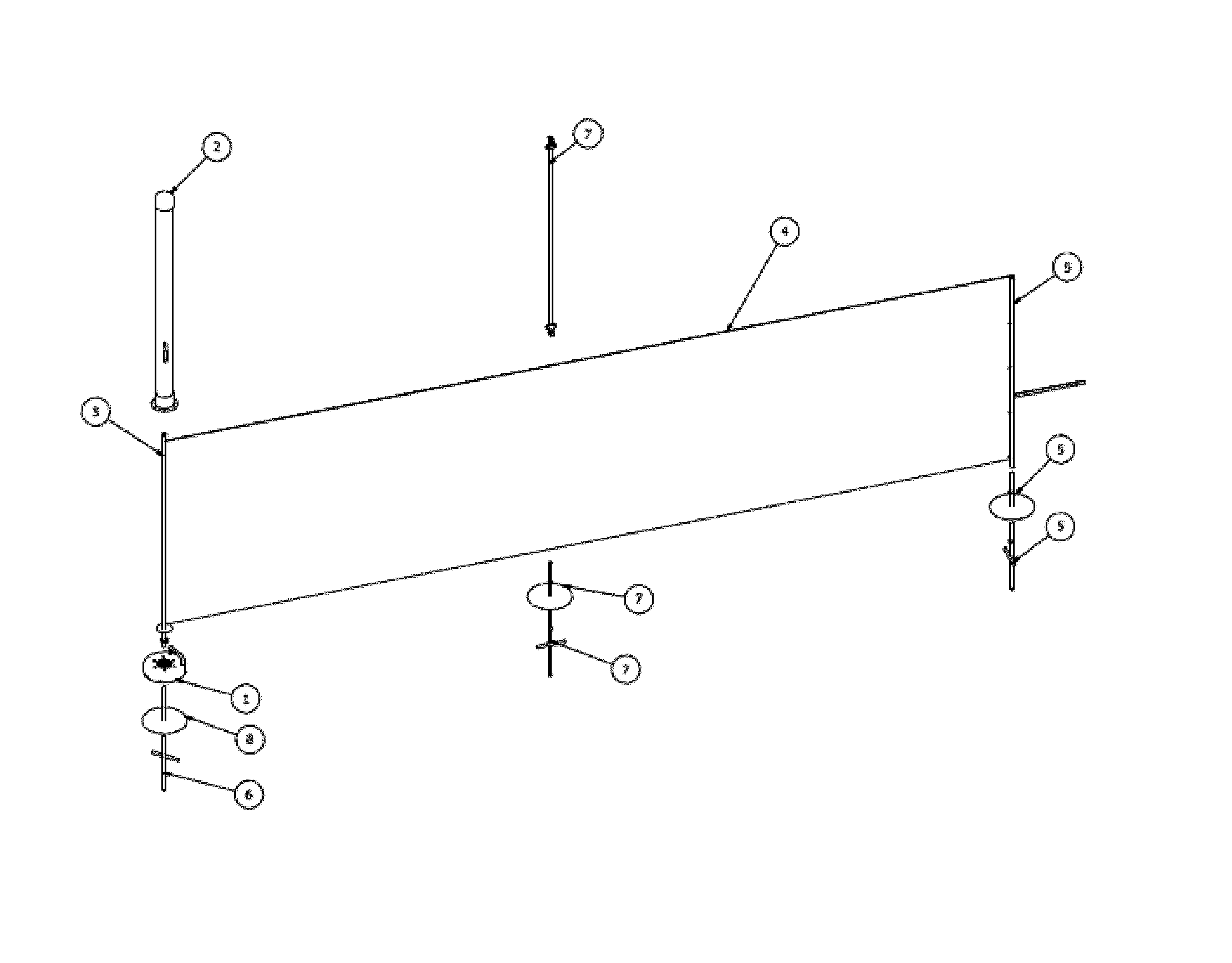
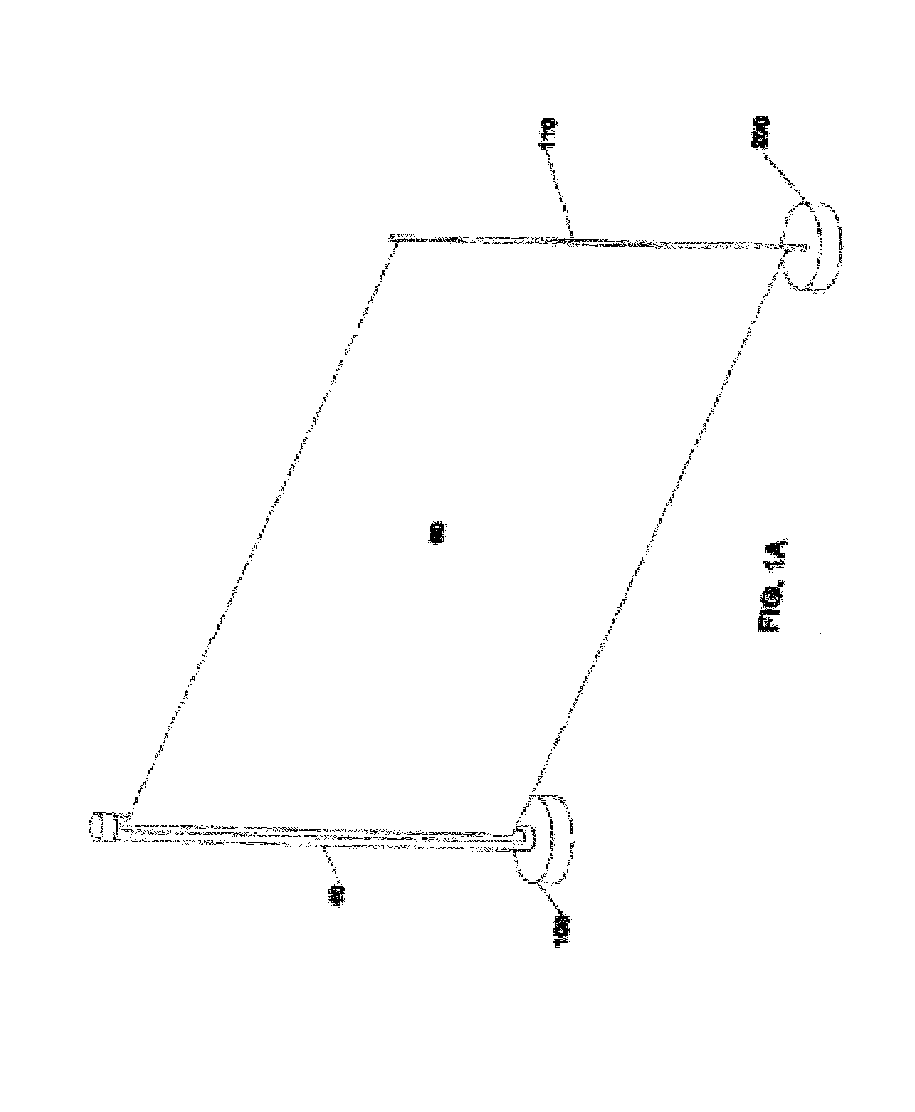
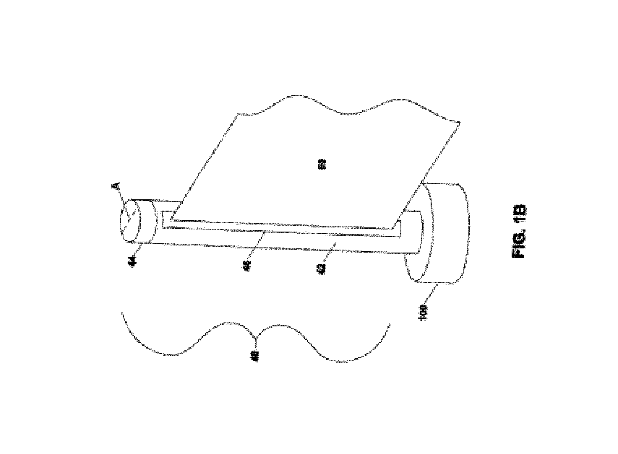
[0031]In general, the invention relates to shield apparatuses that may be used to protect passersby, bystanders, and physical property, e.g., cars and windows, against harm arising from flying debris. The apparatus includes first and second supports having upper and lower ends, a flexible screen, and a retraction mechanism, typically associated with the first support. The screen has opposing vertical edges attached to the supports. The retraction mechanism has a construction that may allow the second support to be pulled toward the first support, e.g., by way of the screen.

[0032]In operation, the shield apparatus may be transported to a grounds region where a device prone to hurl high-flying debris of differing trajectories may be used. The supports are positioned in a substantially vertical orientation at different locations bounding the region, while the screen is maintained in a substantially taut manner between the supports. The screen may serve to block debris hurled during use...


PUM


Abstract

A landscaping device and shield apparatus combination is provided. The landscaping device is powered by an engine and/or motor capable of hurling upward flying debris. The apparatus includes supports, each having an upper end and a lower end. Bases each having a rod insertable up to a bulge into the lower ends of the supports are provided to maintain the supports in a substantially vertical orientation. Also included are: a flexible screen and a retraction mechanism. The retraction mechanism has a construction such so as to provide an automatic locking and automatic retraction assist that a second support may be temporarily locked, and later pulled toward the first support, as desired The landscaping device excludes a stump grinder.

Description

CROSS REFERENCE TO RELATED APPLICATIONS[0001]This is a continuation-in-part of U.S. patent application Ser. No. 14 / 288,928, entitled “GARDENING SAFETY APPARATUS AND METHOD,” filed May 28, 2014, which is a is a continuation-in-part of U.S. patent application Ser. No. 13 / 269,535, entitled “LANDSCAPE SHIELD APPARATUS AND METHOD,” filed Aug. 7, 2011, which is a divisional of U.S. patent application Ser. No. 13 / 049,884, entitled “LANDSCAPE SHIELD APPARATUS AND METHOD,” filed Mar. 16, 2011, the disclosures of which are hereby incorporated by reference in their entirety.BACKGROUND OF THE INVENTION[0002]The invention relates generally to landscaping apparatuses and to methods that provide for a safety measure associated with the use of power landscaping devices. More specifically, the invention relates to the use of power landscaping devices with landscaping apparatuses having a flexible screen to block high velocity debris hurled by the landscaping device from traveling through the screen,...

Claims


Application Information

Patent Timeline
IPC IPC(8): A47G5/02F16P1/02E06B9/40E06B11/04
CPCE06B9/40F16P1/02A47G5/02E06B11/04E04G21/30
Inventor KALINSKI, JAMES JEFFREY
Owner LANDSCAPE SAFETY SYST
Why Eureka
Try Eureka