Emergency safety marker system

a safety marker and electronic technology, applied in the field of emergency safety markers, can solve the problems of suffering the risk of being struck by an approaching motorist, and achieve the effects of avoiding personal injury, enhancing visibility, and enhancing visibility

Active Publication Date: 2016-09-06
STROBE SAVER LLC
View PDF51 Cites 42 Cited by
  • Summary
  • Abstract
  • Description
  • Claims
  • Application Information

AI Technical Summary

Benefits of technology

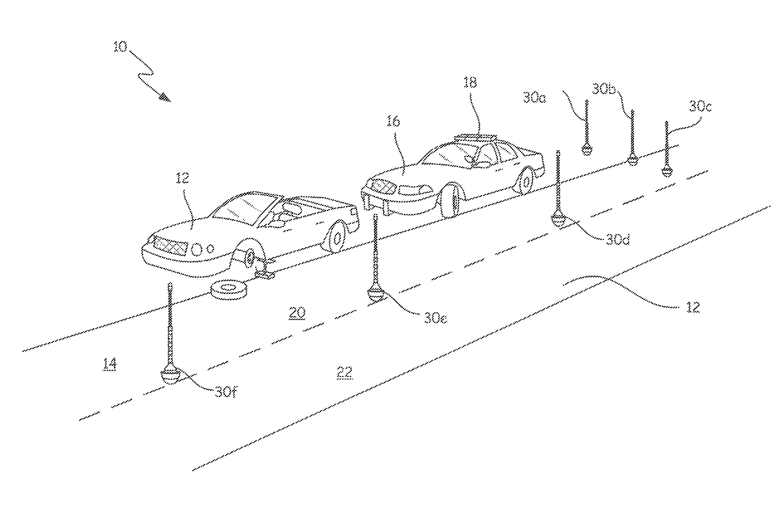
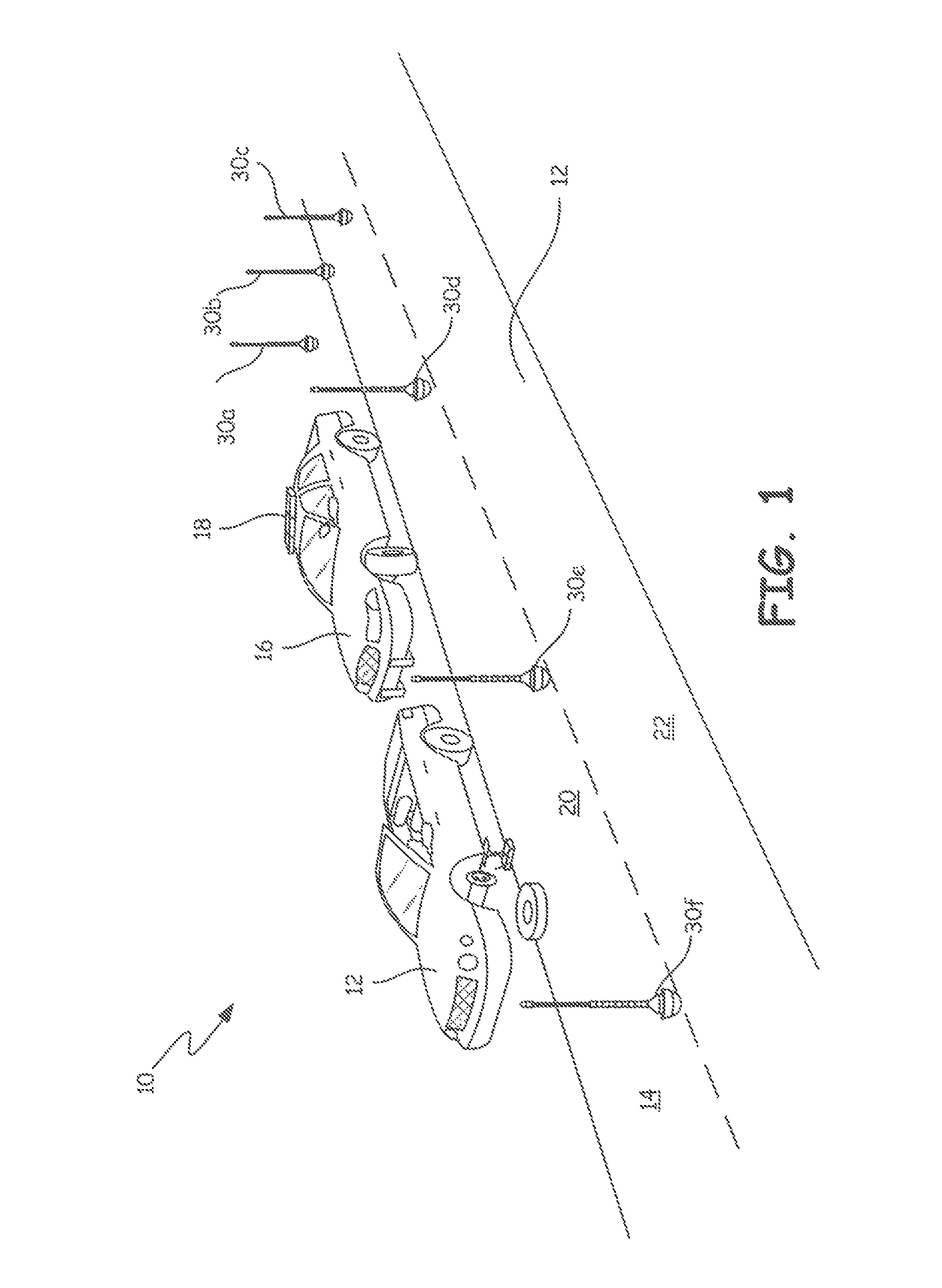
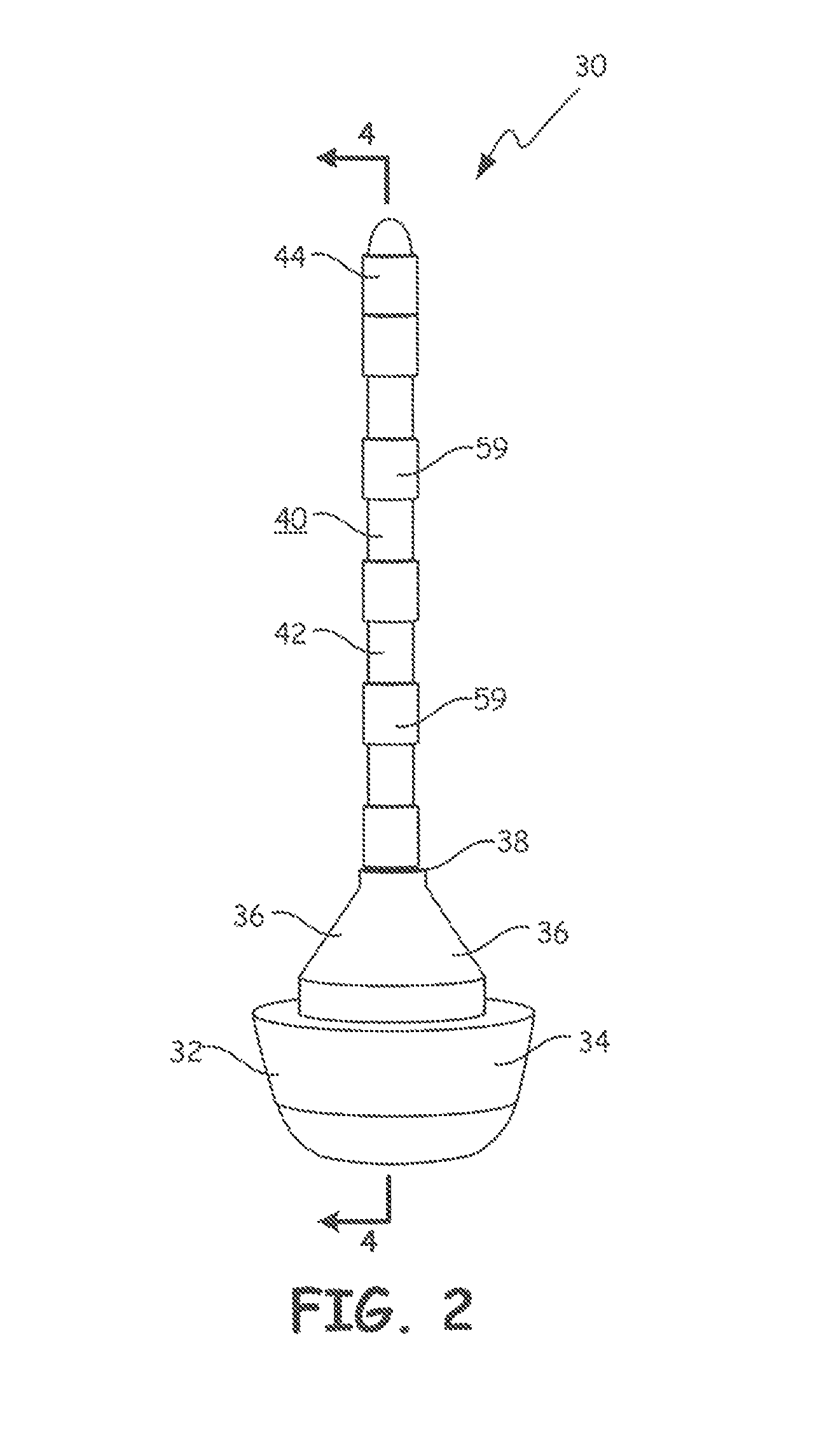
[0026]An electronic lighted safety marker system used by emergency responders to warn motorists on roadways of the presence of an accident scene ahead on the roadway or beside the roadway is provided by the invention. Such markers can be deployed individually or in groups by the emergency responder along the perimeter of the accident scene and ideally ahead of it along the roadway to provide adequate warning to approaching motorists to avoid the accident scene. The markers contain a power source, a light panel, a protective shield for the light panel, and electronic circuitry for controlling the operation of the lights in a predetermined frequency or pattern. One or more of the lights may be colored or operate in a strobe pattern for enhanced visibility for the motorists.
[0027]At the same time, the marker device has a self-righting base. An emergency responder can manually drop or drop via an electro-mechanical device the marker device from his vehicle, and have the marker device stand up in a substantially vertical orientation after it hits the ground. In this manner, the emergency responder need not leave the safety of his vehicle to deploy the marker on or along the roadway and therefore suffer the risk being struck by an approaching motorist.
[0028]The safety marker device should contain a low-impact sensor switch operatively connected to the electronic circuitry to automatically extend the light panel to its optimal height and turn on the lights when the marker device strikes the ground or other hard surface. The lights along the light panel should preferably be visible round a 360° perimeter for enhanced visibility to approaching motorists no matter what is the orientation of the marker device with respect to the roadway and motorists.

Problems solved by technology

In this manner, the emergency responder need not leave the safety of his vehicle to deploy the marker on or along the roadway and therefore suffer the risk being struck by an approaching motorist.

Method used


Image

  • Emergency safety marker system
  • Emergency safety marker system
  • Emergency safety marker system

Examples


embodiment 160

[0112]A spring embodiment 160 for the actor mechanism 54 is shown in FIG. 11. The structure of the stanchion tube 42 and carrier tube 48 are similar to the FIG. 9 embodiment. A compression spring 162 is disposed inside chamber 122 between the bottom wall of stanchion tube 42 and retaining member 164 disposed below the bottom surface of the carrier tube 48 containing the light array wand 44. An electronic solenoid operates actuator arm 166 connected to book 168 which engages recess 170 formed in the bottom surface of retaining member 164.

[0113]When actuated, the low-impact sensor switch 54 / 86 closes its switch to send electrical current to the solenoid actuator 100. This solenoid actuator in turn causes the actuator arm 166 to move to disengage hook 168 from recess 170 in the retaining member 164. This allows the compression spring 162 to expand to its fully length, using its stored energy to push against the bottom surface of the light array wand to raise it inside stanchion tube 42...

embodiment 180

[0115]A jack screw embodiment 180 for the actuator mechanism 54 is shown in FIG. 12. The structure of the stanchion tube 42 and carrier tube 48 are similar to the FIG. 9 embodiment. A base support 182 is mounted to the bottom surface of the carrier tube 48 of the light array wand 44. A threaded column 184 contained inside chamber 122 is attached at its upper end to the base support 182. The bottom end of the threaded column 184 is operably secured to a motor 186 also contained inside chamber 122.

[0116]When actuated, the low-impact sensor switch 54 / 86 closes its switch to send electrical current to motor 186. The energized motor rotates threaded column 184 to raise base support 182 and with it the light array wand inside stanchion tube 42 to its extended position when lips 126 of the carrier tube abut shoulders 128 in stanchion tube. Release pin 138 supports the light array wand in its vertically extended position. Mating female and male contacts complete the electrical circuit to de...

embodiment 320

[0164]Also mounted to upper electronics housing 336 is on / off switch 370. The emergency responder can use this switch 370 to manually turn on and off lights bulbs 338 contained in the hand-held safety marker 320. Unlike safety marker 30, this hand-held embodiment 320 of the safety marker device does not contain a low-impact sensor switch that is actuated when the safety marker is dropped on the ground or other hard surface. Instead, it must be manually turned on.

[0165]Also mounted to upper electronics housing 336 is screamer switch 372. This switch is used by the emergency responder to manually turn on and off the screamer module 366 that emits the emergency warning sound or message if an oncoming motorist strikes the safety marker 320 near the accident scene ad actuates high-impact sensor witch 354.

[0166]Finally day / night switch 374 is mounted to upper electronics housing 336. LED bulbs 338 in particular need to be bright enough during daylight hours to be seen by oncoming motorist...


PUM


Abstract

An electronic lighted safety marker system used by emergency responders to warn motorists of the presence of an accident scene ahead on or beside the roadway is provided by the invention. Such safety marker can be deployed individually or in groups by the emergency responder along the perimeter of the accident scene and ideally ahead of it along the roadway to provide adequate warning to approaching motorists to avoid the accident scene. The safety marker contains a power source, a light panel, a protective shield for the light panel, and electronic circuitry for controlling the operation of the lights in a predetermined frequency or pattern, and may be automatically actuated and self-righting when it is dropped onto the ground or other hard surface. The safety marker can also contain an incursion warning system against incoming vehicles, an early warning radar transponder for sending a warning message to such incoming vehicles, a GPS location detector and transmitter for providing the location of the safety marker and its associated accident scene to a central dispatcher, and a gunshot sensor for detecting the occurrence of gunfire around the accident scene and its location to provide that information to the central dispatcher.

Description

CROSS-REFERENCE TO RELATED APPLICATION[0001]This application claims the benefit of the United States provisional application No. 62 / 016,407 entitled “Emergency Safety Marker System” filed on Jun. 24, 2014, which is hereby incorporated by reference.FIELD OF THE INVENTION[0002]This invention relates generally to flares used by emergency responder personnel to mark an accident scene to warn other people to stay away, and more specifically to electronic safety markers that may be deployed by an emergency responder without risk of physical injury while providing warning to that responder of any reckless motorist approaching the accident scene.BACKGROUND OF THE INVENTION[0003]An integral aspect of daily life is the use of motor vehicles to transport people from one location to another location. Changes in local economies and housing prices have compelled many people to live further from where they work, shop, or seek entertainment. This means that the number of vehicle miles traveled by m...

Claims


Application Information

Patent Timeline
Patent Type & Authority Patents(United States)
IPC IPC(8): G08G1/095G08G1/09F21V21/06F21L4/02
CPCF21L4/02F21V21/06G08G1/09F21V23/0492F21W2111/02F21Y2115/10F21Y2107/30B60Q7/00E01F9/654E01F9/615B60Q1/2657B60Q1/2696
Inventor STAFFORD, JOSEPH V.LAHTONEN, JAN C.ALLEN, BRUCE S.
Owner STROBE SAVER LLC
Why Eureka
Try Eureka