
Passive intermodulation detection

a detection field and intermodulation technology, applied in the field of wireless communication, can solve the problems of less frequent occurrence of pim problems, failure of pim tests, and desensitization of the receiver

Active Publication Date: 2016-09-06
TELEFON AB LM ERICSSON (PUBL)
View PDF10 Cites 60 Cited by
  • Summary
  • Abstract
  • Description
  • Claims
  • Application Information

AI Technical Summary

Benefits of technology

The patent describes a method for measuring intermodulation distortion in a wireless network. The method involves analyzing data collected from multiple data sets and comparing it to statistical distributions. The expected delay of the transmit signals is determined, and the time of collecting samples is determined based on the estimated delay. The measurement indicative of intermodulation distortion is based on the amplitude of the Nth order product of the transmit signals. The method can be performed without disabling live traffic into the receiver. The technical effect of this patent is to provide a reliable and accurate way to measure intermodulation distortion in wireless networks, which can help improve network performance and reduce interference.

Problems solved by technology

Passive intermodulation (PIM) distortion is problematic for multi-band transmitters when intermodulation distortion (IMD) falls into occupied receiver (Rx) channels, which desensitizes the receiver.
Multi-band signals are an important characteristic of LTE and multi-standard radios, so the occurrence of PIM problems will be more frequent than with previous cellular wireless communication standards.
Failed PIM tests could be a result of failing components, over or under-tightened connectors, or dirty connectors, including metal flakes.
Other PIM sources can develop with aging, such as corrosion.
In this case the PIM source cannot be removed, so the antenna may need to be re-oriented or the transmit power decreased.
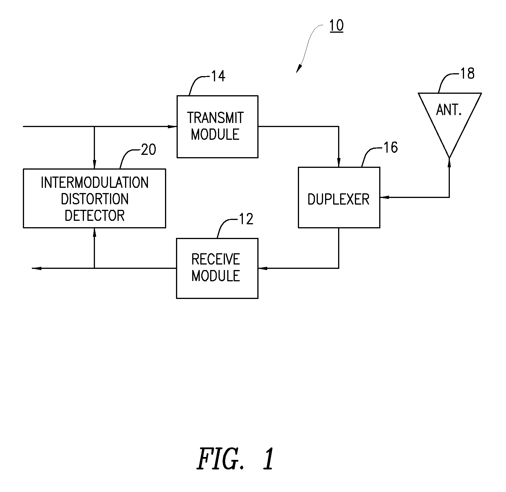
In a base station, the high power transmit signal of the base station transmitter is typically a source of PIM distortion when the transmit signal passes through a passive device that exhibits some non-linearity.
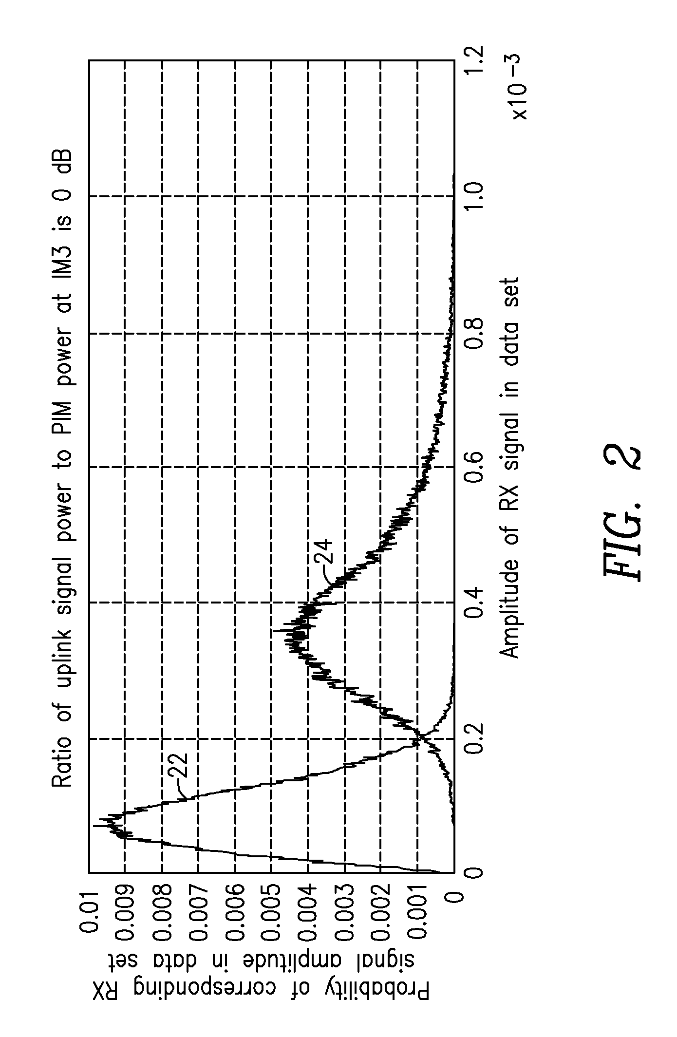
A problem with these two approaches is that their models are trained with a PIM signal that is typically weaker than the uplink signal, even when the uplink signal is only noise and in-band interference.

Method used


Image

  • Passive intermodulation detection
  • Passive intermodulation detection
  • Passive intermodulation detection

Examples


Embodiment Construction

[0019]Before describing in detail example embodiments that are in accordance with the present disclosure, it is noted that the embodiments reside primarily in combinations of apparatus components and processing steps related to detection of intermodulation distortion such as passive intermodulation distortion affecting a receiver in a radio. Accordingly, the system and method components have been represented where appropriate by conventional symbols in the drawings, showing only those specific details that are pertinent to understanding the embodiments of the present disclosure so as not to obscure the disclosure with details that will be readily apparent to those of ordinary skill in the art having the benefit of the description herein.

[0020]As used herein, relational terms, such as “first” and “second,”“top” and “bottom,” and the like, may be used solely to distinguish one entity or element from another entity or element without necessarily requiring or implying any physical or lo...


PUM


Abstract

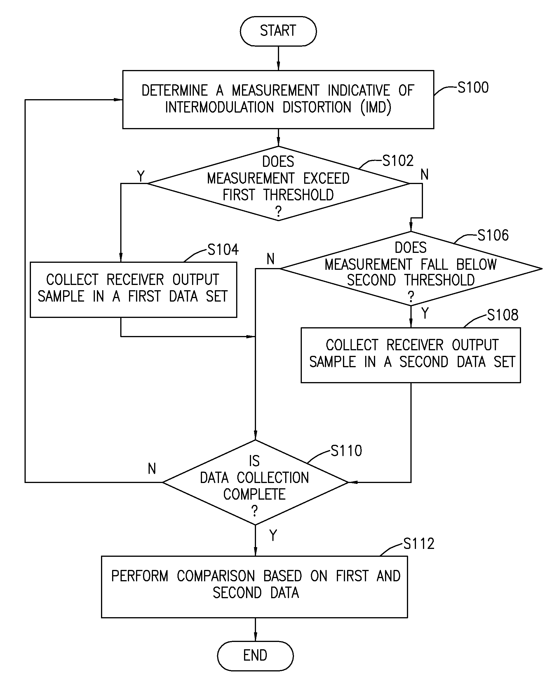
A method, apparatus and receiver for detecting intermodulation distortion (IMD) affecting a received signal in a wireless receiver are provided. One method includes determining a measurement indicative of IMD based on at least one transmit signal. When the measurement indicative of IMD exceeds a first pre-determined level, at least one sample of an amplitude of a signal output by the wireless receiver is collected in a first data set. When the measurement indicative of intermodulation distortion does not exceed a second pre-determined level, the second predetermined level being less than the first predetermined level, at least one sample of an amplitude of the signal output by the wireless receiver is collected in a second data set. A comparison is performed based on data of the first data set and on data of the second data set to determine a measure of IMD.

Description

FIELD[0001]The present invention relates wireless communications and in particular to a method and system for determining an extent of intermodulation distortion in a wireless receiver.BACKGROUND[0002]Passive intermodulation (PIM) occurs when signals are present in a passive device that exhibits some non-linear behavior. In a base station, such as an evolved node B (eNB) of a long term evolution (LTE) wireless communication system, high power signals can cause measureable PIM due to non-linear behavior of components such as RF transmission cables, duplexers, connectors, antenna, or some object external to an antenna of the base station.[0003]Passive intermodulation (PIM) distortion is problematic for multi-band transmitters when intermodulation distortion (IMD) falls into occupied receiver (Rx) channels, which desensitizes the receiver. Multi-band signals are an important characteristic of LTE and multi-standard radios, so the occurrence of PIM problems will be more frequent than wi...

Claims


Application Information

Patent Timeline
Patent Type & Authority Patents(United States)
IPC IPC(8): G01R31/08H04B1/10G06F11/00G08C15/00H04J1/16H04J3/14H04B17/26
CPCH04B1/1027H04B17/26H04B1/109H04J11/0023
Inventor WYVILLE, MARK WILLIAM
Owner TELEFON AB LM ERICSSON (PUBL)
Learn More