Friction pad assembly for disk brake

a technology of friction pad and disk brake, which is applied in the direction of friction lining, mechanical equipment, transportation and packaging, etc., can solve the problems of loss of braking torque transmission, inability to provide stable braking characteristics, and noise of braking, so as to reduce the thickness of the torque receiving plate, reduce the weight of the parts used, and reduce the weight

Inactive Publication Date: 2016-09-13
AKEBONO BRAKE IND CO LTD
View PDF33 Cites 9 Cited by
  • Summary
  • Abstract
  • Description
  • Claims
  • Application Information

AI Technical Summary

Benefits of technology

[0011]Thus, the flat-plate shaped torque receiving plate for applying the pressure to the plurality of lining assemblies must have a thickness of sufficient rigidness and, when not, there is a possibility that it is difficult to apply the pressure equally to the plurality of lining assemblies. In the case of the torque receiving plate the thickness of which is increased for enhanced rigidity, the weight is increased to thereby incur the increased cost.
[0012]The invention aims at solving the above problem and thus it is an object of the invention to provide a friction pad assembly for a disk brake which, by easing the working precision of parts used and reducing the weights of the parts, can realize the reduced cost and enhanced productivity.Solution to Problem
[0027]While the clearance hold mechanism is provided in the vicinity of the central portion of the torque receiving plate with its outer peripheral portion fixable to the guide plate spaced a clearance from the back plate portion of the lining assembly and guide plate, this mechanism can support a portion of the pressure applied to the torque receiving plate in the vicinity of the central portion of the torque receiving plate. Thus, the rigidity of the torque receiving plate with its outer peripheral portion fixed to the guide plate is higher than when the clearance hold mechanism 40 is not provided, thereby being able to reduce the plate thickness of the torque receiving plate itself.
[0028]Therefore, due to the eased working precision of parts used and the reduced weight thereof, reduced cost and enhanced productivity can be realized.

Problems solved by technology

In a disk brake apparatus for a railway vehicle, since a disk rotor and a friction pad assembly for a disk brake are large in size, when a lining member to be pressed against the disk rotor is formed of an integral part, such area of the lining member as is not contacted with the disk rotor is increased due to the undulation of the disk rotor caused by frictional heat or the like, whereby stable frictional area cannot be maintained and thus stable braking characteristics cannot be provided.
Also, when the lining member is rotated unexpectedly due to contact with the disk rotor, the loss transmission of the braking torque can occur and braking noises can occur.
This causes the need of a device for restricting the rotation of the lining member, which increases the number of parts.
The increased number of parts incurs the increased cost and the increased the number of assembling steps, thereby lowering the productivity.

Method used


Image

  • Friction pad assembly for disk brake
  • Friction pad assembly for disk brake
  • Friction pad assembly for disk brake

Examples


Embodiment Construction

[0038]Description is given specifically of a friction pad assembly for a disk brake according to an embodiment of the invention with reference to the drawings.

[0039]FIGS. 1 to 7 show a friction pad assembly for a disk brake according to an embodiment of the invention, and FIGS. 8(a) to 8(c) are arrow views to explain the procedure for assembling unit friction pad assemblies constituting a friction pad assembly for a disk brake.

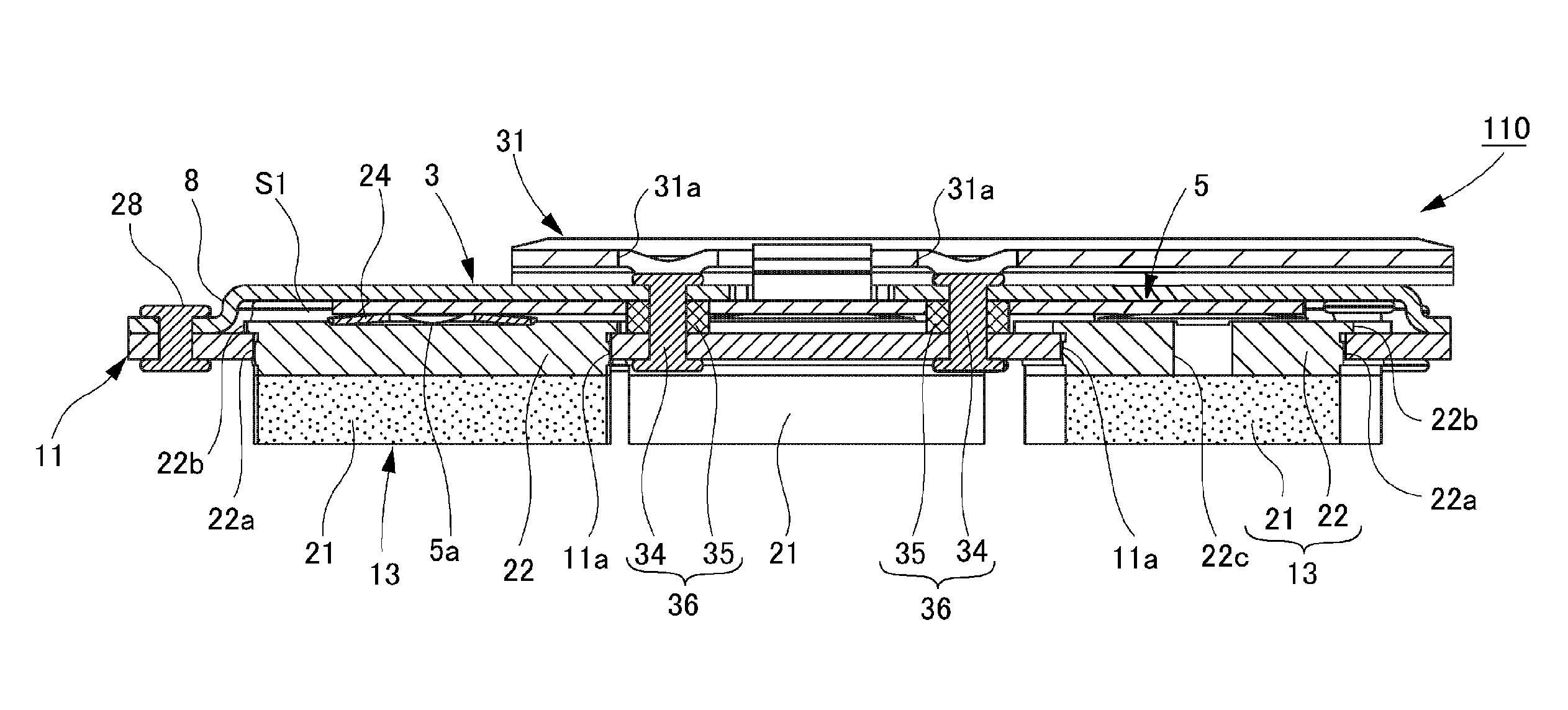
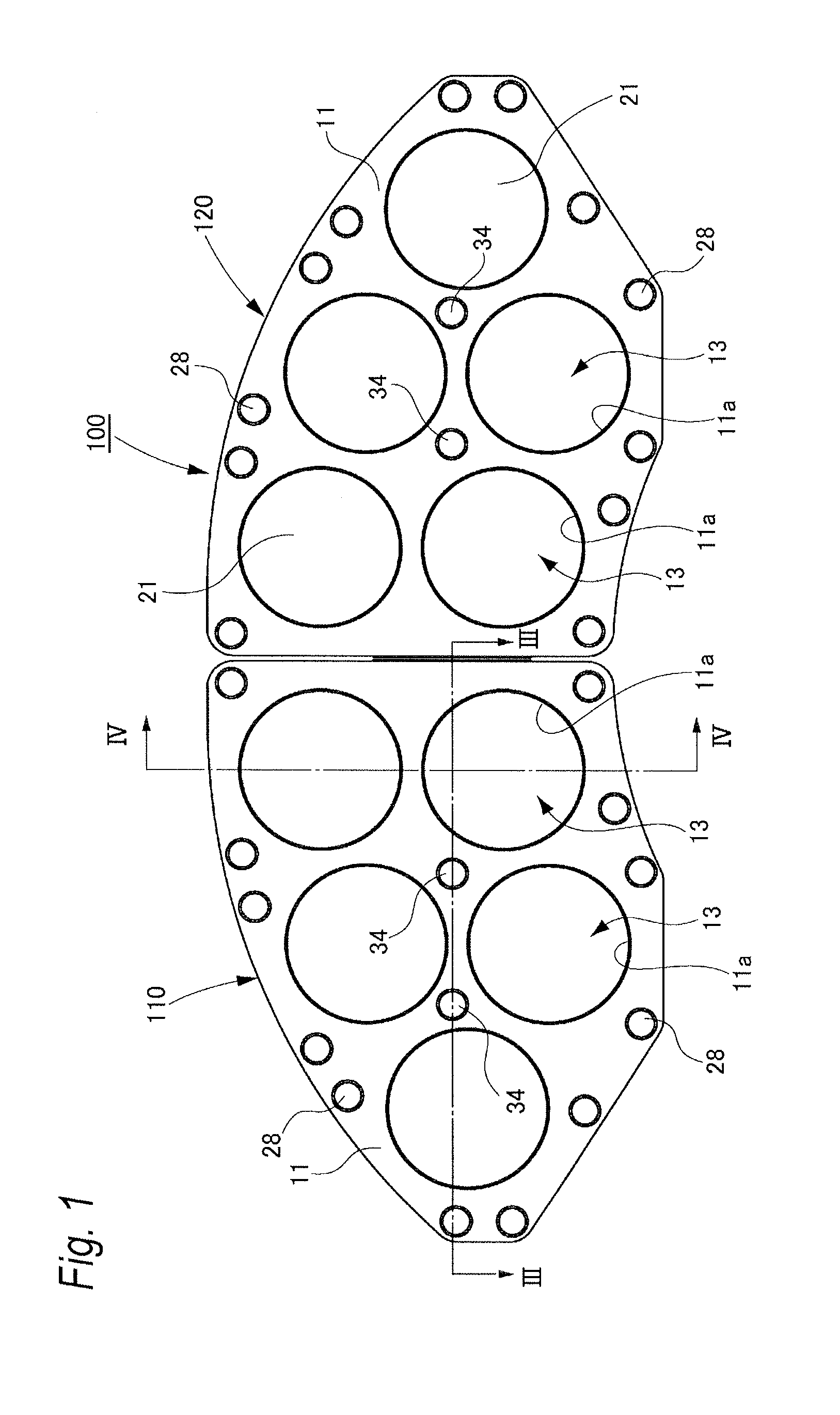
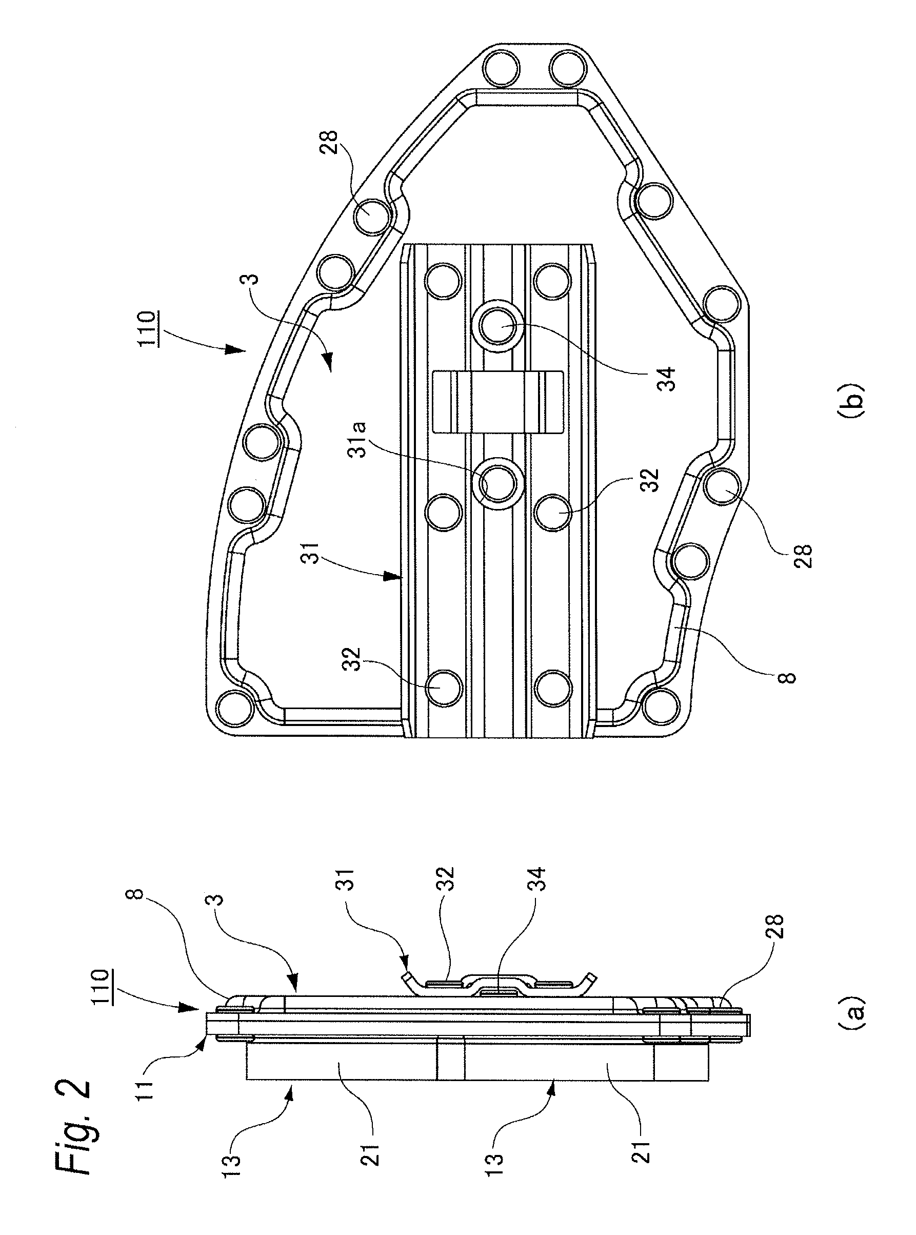
[0040]As shown in FIG. 1, a friction pad assembly for a disk brake 100 according to the embodiment is used for a railway vehicle disk brake apparatus and is composed of two unit friction pad assemblies 110 and 120 arranged adjacent to each other in the peripheral direction of a disk rotor (not shown) on an axle. The unit friction pad assemblies 110 and 120 are structured similarly. They are respectively disposed opposed to the disk rotor and can be driven to advance and retreat with respect to the disk rotor by an actuator built in a brake caliper (not shown)....


PUM


Abstract

A unit friction pad assembly constituting a disk brake friction pad assembly includes a lining assembly which is oscillatably inserted into the guide hole portion of a guide plate to transmit a braking torque from a plate engagement portion to the guide plate and is urged toward the guide plate by a spring member, and a clearance hold mechanism for holding a clearance between the guide plate and torque receiving plate.

Description

TECHNICAL FIELD[0001]The present invention relates to an improved friction pad assembly for a disk brake.BACKGROUND ART[0002]A disk brake apparatus includes a disk rotor to be fixed to an axle, a disk brake friction pad assembly constituted of a torque receiving plate disposed opposed to the disk rotor and a lining member assembled to the disk rotor side surface of the torque receiving plate, and a brake caliper to be fixed to a vehicle body frame and including therein an actuator for advancing and retreating the torque receiving plate with respect to the disk rotor, whereby a braking force is generated by sliding friction caused when the torque receiving plate is advanced toward the disk rotor to thereby press the lining member against the disk rotor.[0003]In a disk brake apparatus for a railway vehicle, since a disk rotor and a friction pad assembly for a disk brake are large in size, when a lining member to be pressed against the disk rotor is formed of an integral part, such are...

Claims


Application Information

Patent Timeline
Patent Type & Authority Patents(United States)
IPC IPC(8): F16D69/04B61H5/00F16D65/092
CPCF16D69/04B61H5/00F16D65/092F16D69/0408
Inventor MAEHARA, TOSHIFUMI
Owner AKEBONO BRAKE IND CO LTD
Why Eureka
Try Eureka