Ball valve having an external seal arrangement, particularly for use in motor vehicle refrigerant circuits

Active Publication Date: 2016-09-13
HANON SYST
View PDF11 Cites 3 Cited by
  • Summary
  • Abstract
  • Description
  • Claims
  • Application Information

AI Technical Summary

Benefits of technology

[0020]An additional advantage of the invention consists in that, in the ball valve, the actuator is a sufficient distance from the valve body due to spacing resulting from the shaft, so that the thermal stress on the electrical components of the actuator can be minimized, and operation at high temperature and also at low temperature is as a result also satisfactorily guaranteed.
[0021]The oil, as sealing fluid, thus forms an intermediate seal in the form of an oil pocket with a cavity for the sealing fluid, which is partially formed by a diaphragm. The valve type is suitable for producing two/two, three/two and four/two way valves by modifying the actuator and the ball geometry.
[0022]The actuator with the motor gearbox and the electronics is thermally separated from the valve, for example, by the distance between the actuator and the valve housing, by an insulating shaft made of poorly heat conducting

Problems solved by technology

To date, hardly any components suitable for practical use are available in the prior art, and consequently proven components have to be modified and adapted to the new challenges.
Very generally, ball valves are known to be associated with tightness problems relating to the so-called internal tightness, which concerns the flow of the fluid to be regula

Method used


Image

  • Ball valve having an external seal arrangement, particularly for use in motor vehicle refrigerant circuits
  • Ball valve having an external seal arrangement, particularly for use in motor vehicle refrigerant circuits
  • Ball valve having an external seal arrangement, particularly for use in motor vehicle refrigerant circuits

Examples


Embodiment Construction

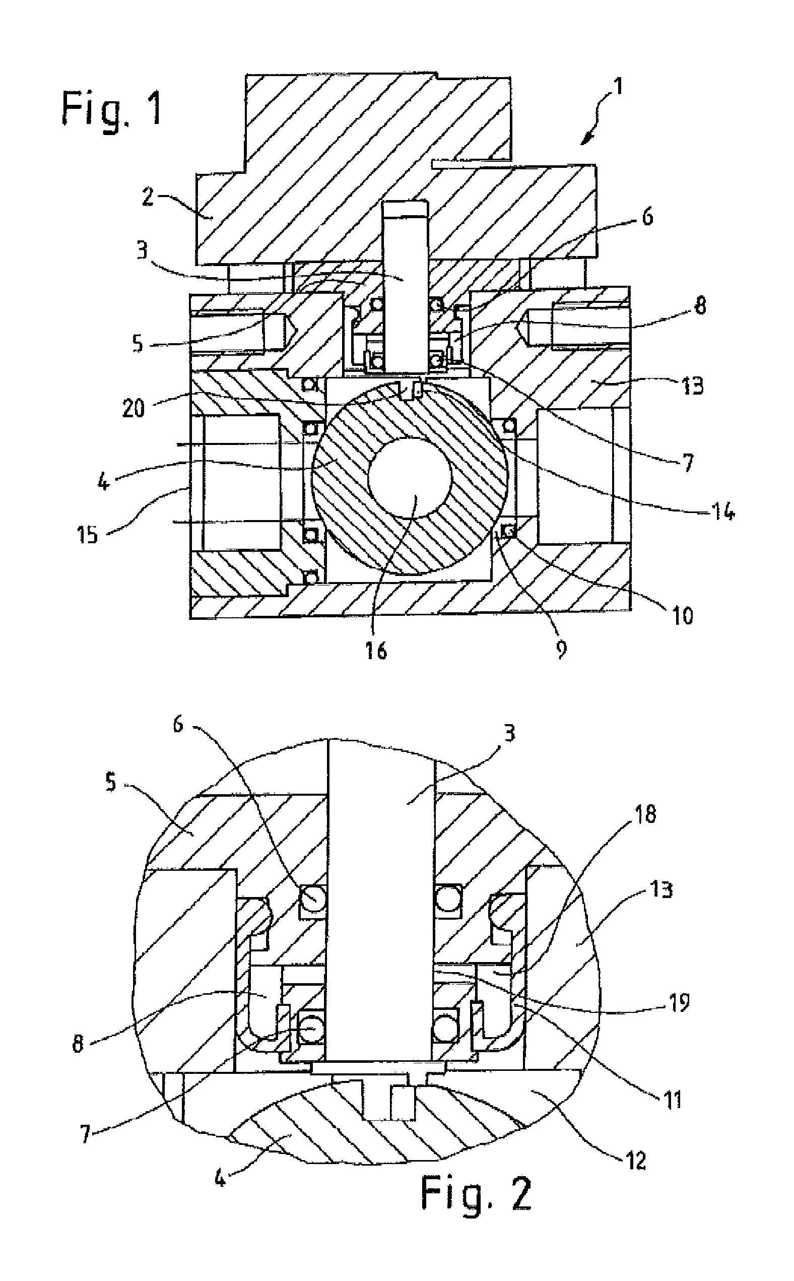
[0034]In FIG. 1, a ball valve 1 is represented in cross section with its essential components. The ball valve 1 has an actuator 2, which turns a shaft 3 depending on the desired degree of flow through the valve. The shaft 3 is connected by a lug 20, which engages in an engagement notch 14 of the ball 4. In the ball 4, the ball passage channel 16 is formed, through which the fluid flows, when the valve position of the ball valve 1 is open, from the inlet of the valve to the outlet of the valve.

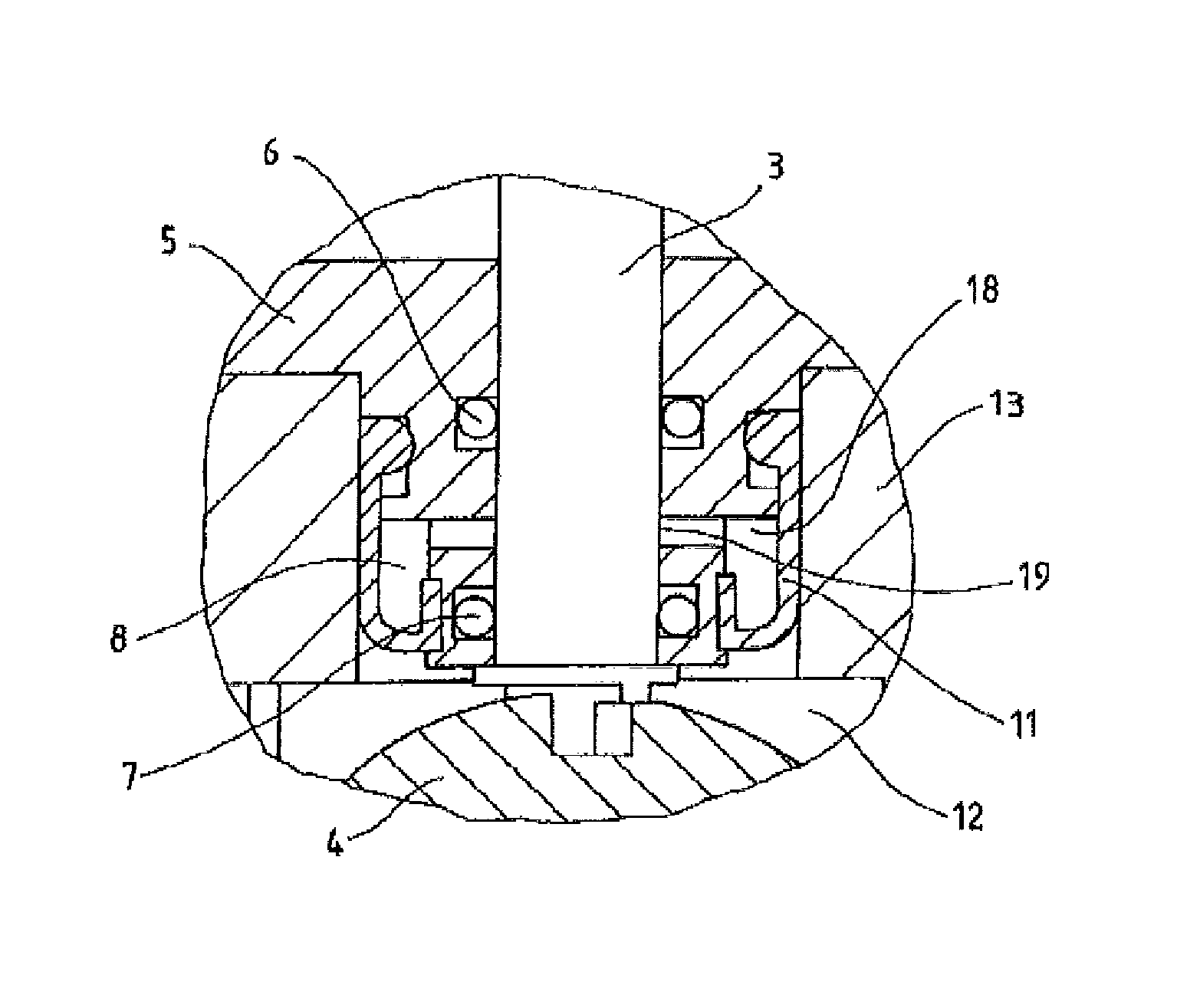
[0035]The shaft 3 is rotatably mounted about its axis in a shaft bearing 5. The shaft bearing 5 has an external shaft seal 6 and an internal shaft seal 7, between which a fluid shaft seal 8 is formed. The seal arrangement of external shaft seal 6, internal shaft seal 7 and intermediate fluid shaft seal 8 is used to prevent the discharge of fluid flowing through the ball valve 1 as a result of play of the shaft 3 in the shaft bearing 5. This sealing system is also referred to as external double ...


PUM


Abstract

A ball valve (1), particularly for use in motor vehicle refrigerant circuits, having an actuator (2), a shaft (3) including a shaft bearing (5), a ball (4) including a ball passage (16), and a valve housing (13). A fluid shaft seal (8) is arranged in the shaft bearing (5) between an upper shaft seal (6) and a lower shaft seal (7), wherein the fluid shaft seal (8) is formed by a cavity (18) in which a sealing fluid is provided, and that the sealing fluid is in contact with the shaft (3) in a sealing region (19) such that the sealing fluid has a sealing effect in the axial direction, wherein the cavity (18) is at least partially formed by a diaphragm (11) and is limited on the shaft (3) by the shaft seals (6, 7), and that the diaphragm (11) is formed in such a way that pressure can be applied to the side facing away from the sealing fluid.

Description

CROSS-REFERENCE TO RELATED APPLICATIONS[0001]This application is a United States national phase application based on PCT / EP2012 / 074151 filed Nov. 30, 2012 which claims the benefit of German Patent Application No. DE 10 2011 055 892.6 filed Nov. 30, 2011 and German Patent Application No. DE 10 2012 111 467.6 filed Nov. 27, 2012. The entire disclosures of the above applications are hereby incorporated herein by reference.TECHNICAL FIELD[0002]The invention relates to a ball valve, particularly for use in motor vehicle refrigerant circuits.BACKGROUND OF THE INVENTION[0003]Ball valves have an actuator, which drives a shaft mounted in a shaft bearing, which transfers the rotation to the valve element which is formed by a ball with a ball passage channel. The components are mounted in a valve housing, and ball valves are considered robust and cost effective and they are used for numerous applications.[0004]In modern refrigerant systems for motor vehicle air conditioners, modern functionali...

Claims


Application Information

Patent Timeline
IPC IPC(8): F16K5/06F16K41/00F16K41/10
CPCF16K5/0647F16K5/0694F16K41/003F16K41/106F16K5/14F25B41/20F16K5/0642F16K27/067
Inventor LE PELLEC, CORINNE
Owner HANON SYST
Why Eureka
Try Eureka