Low deflection sputtering target assembly and methods of making same

a low-deflection, sputtering target technology, applied in the direction of diaphragms, metallic material coating processes, non-electric welding apparatuses, etc., can solve the problems of excessive stress on accompanied targets, and significant heat build-up in the target area, so as to minimize the thermal stress at the target/backing plate interface and the effect of assembly bowing

Active Publication Date: 2015-06-18
TOSOH SMD
View PDF1 Cites 4 Cited by
  • Summary
  • Abstract
  • Description
  • Claims
  • Application Information

AI Technical Summary

Benefits of technology

[0011]The target and top layer of the laminated backing plate, adapted for contiguous mating with the target, have a difference in their thermal expansion coefficients of about 22×10−6 cm / cm / ° C. or less. By provision of a matched target and backing plate, thermal stress at the target / backing plate interface and bowing of the assembly are minimized during joining and sputtering operation.

Problems solved by technology

The ejection of these materials from the target is accompanied by significant heat build-up in the target area.
Due to the differing coefficients of thermal expansion (“CTE”) of the target and backing plate members, the high heat levels attained by the target during high power sputtering result in excessive stress exerted along the target / backing plate interface.
Warpage and differential shrinkage of both target and backing plate members may occur despite the cooling function, resulting in severely impeded cooling of the target with attendant target failure.

Method used


Image

  • Low deflection sputtering target assembly and methods of making same
  • Low deflection sputtering target assembly and methods of making same
  • Low deflection sputtering target assembly and methods of making same

Examples


Embodiment Construction

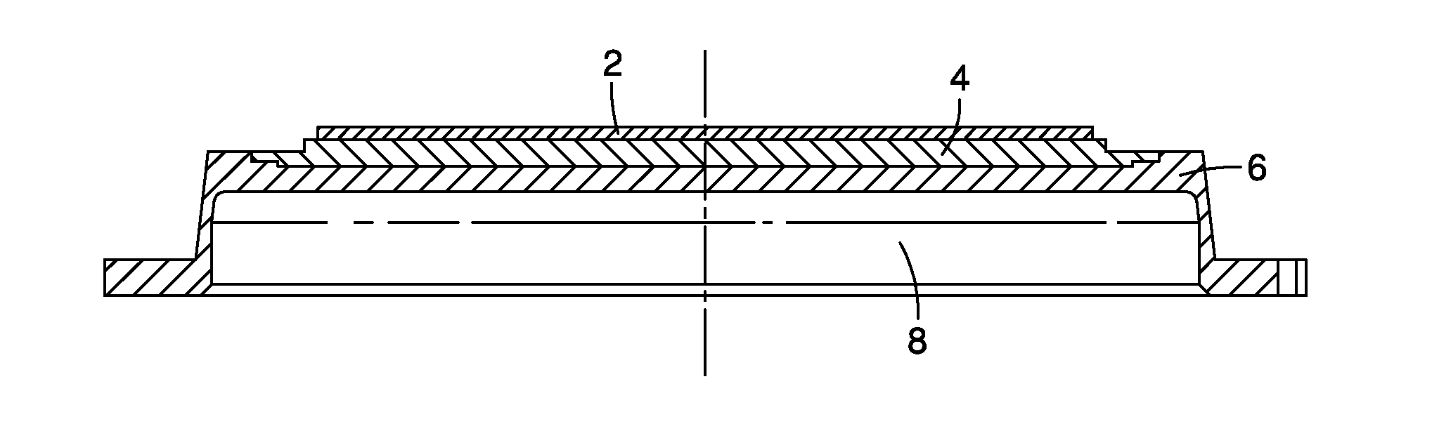
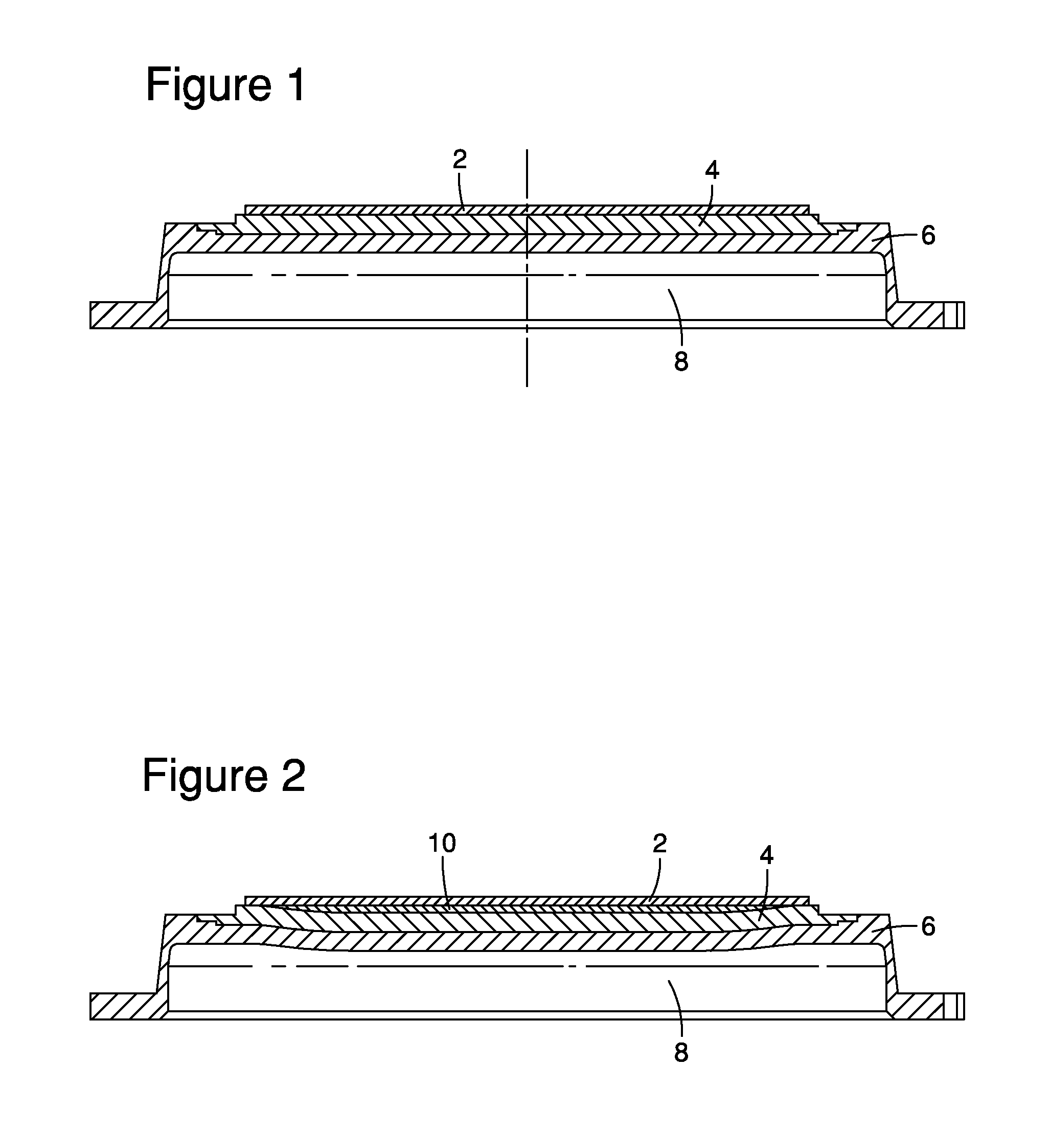
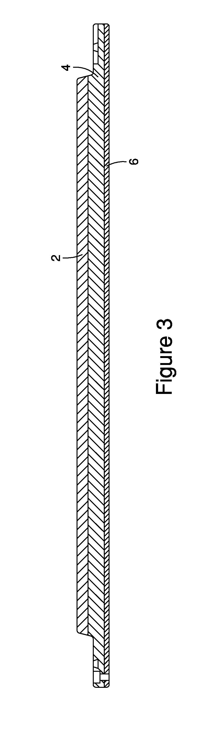
[0019]Turning first to FIG. 1 and FIG. 3 of the drawings, target / backing plate assemblies are shown in accordance with one embodiment of the invention. The assembly comprises a target material 2 having a surface composed of the desired sputtering material. A laminated or composite backing plate assembly is shown and comprises a first material 4, defining a first or top layer of the backing plate assembly that is superposed over a second backing plate material, material 6. In FIG. 1, a cooling chamber 8 is provided in heat exchange relation with the bottom surface of the second backing plate material 6 so as to aid in cooling of the assembly during the sputtering operation. As shown, the materials 4 and 6 can be bonded along their interface by conventional means such as solder bonding, diffusion bonding, brazing, coating, electroplating, etc. The target 2 may be bonded to the top side of first material 4 of the backing plate assembly by conventional means such as solder bonding, diff...


PUM

PropertyMeasurementUnit
thicknessaaaaaaaaaa
coefficient of thermal expansionaaaaaaaaaa
CTEaaaaaaaaaa

Abstract

Described is a design and method for producing a sputtering target assembly with low deflection made from target material solder bonded to composite backing plate with coefficient of thermal expansion (CTE) matching the target material. The composite backing plate is composite configuration composed of at least two different materials with different CTE. The composite backing plate, after plastic deformation, if necessary, has a CTE matching the target material and low and desirable deflection in the bonding process, and therefore, resulting in a low deflection and low stress target material bonded to composite backing plate assembly. The method includes manufacturing composite backing plate with a flat bond surface, heat treating of target blank and composite backing plate to achieve desirable shape of bond surfaces, solder bonding target to a backing plate, and slowly cooling the assembly to room temperature. Matching CTE in both target material and backing plate eliminates the problem of CTE mismatch and prevents the assembly from deflection and internal stress.

Description

CROSS REFERENCE TO RELATED APPLICATION[0001]This PCT application claims the priority benefit of U.S. Provisional Patent Application Ser. No. 61 / 598,595 filed Feb. 14, 2012.FIELD OF INVENTION[0002]The present invention pertains to a sputter target and composite backing plate wherein the target and backing plate component located contiguous to the target are thermally matched with each other to minimize thermal stress occurring along the target / backing plate interface.BACKGROUND OF THE INVENTION[0003]Sputtering as a means to deposit thin films of a desired material on a substrate has become important in integrated circuits. In a sputtering system, material to be deposited on a substrate is removed from a sputter target by bombardment of the target with excited ions in the plasma state. Atoms or molecules of the target material are ejected from the target and are deposited on a workpiece or substrate. The ejection of these materials from the target is accompanied by significant heat bu...

Claims


Application Information

Patent Timeline
Patent Type & Authority Applications(United States)
IPC IPC(8): H01J37/34C25D7/00B23K20/12B23K20/00B23K1/00B23K20/02
CPCH01J37/3417H01J37/3429B23K1/0008C25D7/00B23K20/122B23K20/002B23K20/02B23K20/129B23K2103/10B23K2103/18B23K2103/14B23K2103/08B23K2103/56
Inventor YUAN, YONGWENIVANOV, EUGENE Y.
Owner TOSOH SMD
Why Eureka
Try Eureka