
Apparatus and Method for Controlling a Gas Stream Temperature or Rate of Temperature Change

a technology of attemperation or temperature change, applied in mechanical equipment, steam engine plants, machines/engines, etc., can solve the problems of significant thermal stress event for the hrsg casing and internals, negative impact on the piping and steam turbine components, and thermal stress to the infrastructure transporting these gas streams. to achieve the effect of reducing thermal stress

Active Publication Date: 2020-03-05
ELECTRIC POWER RES INST INC
View PDF4 Cites 1 Cited by
  • Summary
  • Abstract
  • Description
  • Claims
  • Application Information

AI Technical Summary

Benefits of technology

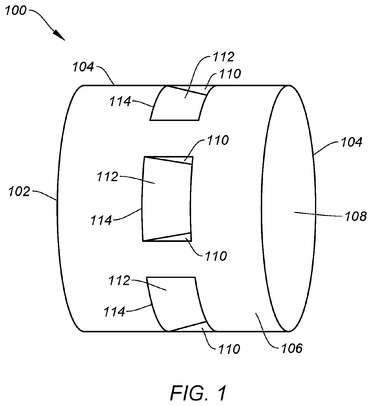
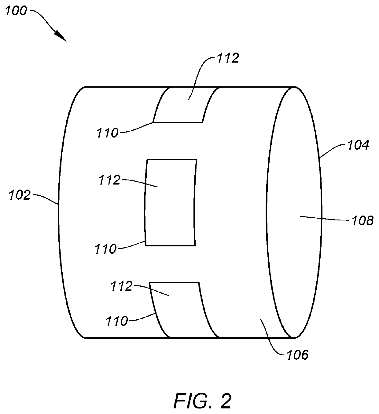
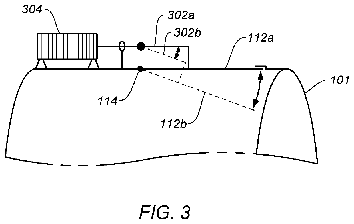
The present invention provides an apparatus and method for controlling the temperature of a gas stream passing through a gas duct. The apparatus includes a body with a plurality of openings and associated shutters that can be opened to create lower pressure areas behind the shutters and pull a second gas into the gas duct, thereby controlling the flow rate of the second gas through each opening and thus the temperature of the gas stream. The apparatus can be used to minimize thermal stress on downstream heat recovery steam generators during startup and other transient operations of a gas turbine.

Problems solved by technology

In many industrial applications, gas streams have extremely high temperatures, resulting in thermal stress to infrastructure transporting these gas streams, including, but not limited to, metal pipes, metal casings, and the like.
This temperature rise can result in a significant thermal stress event for the HRSG casing and internals.
These steam temperature excursions during startup have also had a negative impact on the piping and steam turbine components.
Moreover, the demand for flexible operation has resulted in combined-cycle units being subjected to an unprecedented number of startup cycles that were not anticipated in the original plant design, thus increasing the number of thermal stress events for the HRSG.

Method used


Image

  • Apparatus and Method for Controlling a Gas Stream Temperature or Rate of Temperature Change
  • Apparatus and Method for Controlling a Gas Stream Temperature or Rate of Temperature Change
  • Apparatus and Method for Controlling a Gas Stream Temperature or Rate of Temperature Change

Examples


Embodiment Construction

[0029]The present invention is more fully described below with reference to the accompanying Figures. While the invention will be described in conjunction with particular embodiments, it should be understood that the invention includes alternatives, modifications, and equivalents. Accordingly, the following description is exemplary in that several embodiments are described (e.g., by use of the terms “preferably,”“for example,” or “in one embodiment”), but this description should not be viewed as limiting or as setting forth the only embodiments of the invention, as the invention encompasses other embodiments not specifically recited in this description. Further, the use of the terms “invention,”“present invention,”“embodiment,” and similar terms throughout this description are used broadly and are not intended to mean that the invention requires, or is limited to, any particular aspect being described or that such description is the only manner in which the invention may be made or ...


PUM


Abstract

The invention provides various designs of an apparatus and method for attemperating a gas stream temperature. The apparatus of the present invention provides a body through which a gas stream passes that permits, as desired, a second gas, such as gas outside of the gas duct or such as ambient air, to be added to the main gas stream to attemperate the temperature of the main gas stream. The body or device may be referred to as a variable eductor having a plurality of openings through which a second gas may pass into the main gas stream. The openings may be opened or closed, and the variable eductor provides control over which openings and the degree to which each opening is opened. In some designs the variable eductor is inserted between two portions of a gas duct. The variable eductor has widespread application, such as downstream of a gas turbine to attemperate the exhaust gas temperature during startup.

Description

BACKGROUND OF THE INVENTIONField of the Invention[0001]The invention in its various embodiments relates generally to an apparatus and method for attemperating or controlling the temperature of a gas stream. In particular, the invention in its various embodiments relates to a variable eductor that provides for the addition of a gas to an existing gas stream to attemperate or control the temperature of the gas stream, such as the temperature of an exhaust gas stream from a gas turbine prior to entering a heat recovery stream generator, for example, during startup.Description of Related Art[0002]In many industrial applications, gas streams have extremely high temperatures, resulting in thermal stress to infrastructure transporting these gas streams, including, but not limited to, metal pipes, metal casings, and the like. For example, during startup of a gas turbine, exhaust gas temperatures exiting the gas turbine into the heat recovery stream generator (HRSG) may climb to almost 1000°...

Claims


Application Information

Patent Timeline
Patent Type & Authority Applications(United States)
IPC IPC(8): F01K23/10F02C7/18
CPCF02C7/18F01K23/101F01D25/305F02C7/141F05D2260/601Y02E20/16F02C6/18
Inventor QUINTRELL, MERRILL STANTON
Owner ELECTRIC POWER RES INST INC
Learn More