Boiler tube reinforcement device and boiler tube reinforcement method

Inactive Publication Date: 2018-09-06
THE CHUGOKU ELECTRIC POWER CO INC
View PDF7 Cites 1 Cited by
  • Summary
  • Abstract
  • Description
  • Claims
  • Application Information

AI Technical Summary

Benefits of technology

[0008]According to the present disclosure, it becomes possible to reinforce a boiler tube

Problems solved by technology

When the boiler for power generation continues to be used over a long period of time, creep-fatigue damage is created in the boiler tubes according to the ther

Method used


Image

  • Boiler tube reinforcement device and boiler tube reinforcement method
  • Boiler tube reinforcement device and boiler tube reinforcement method
  • Boiler tube reinforcement device and boiler tube reinforcement method

Examples


Example

First Embodiment

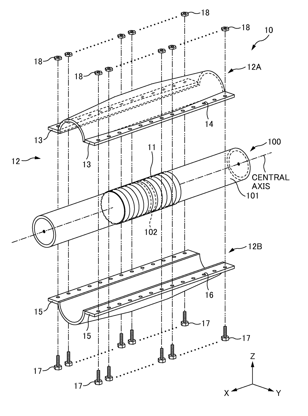
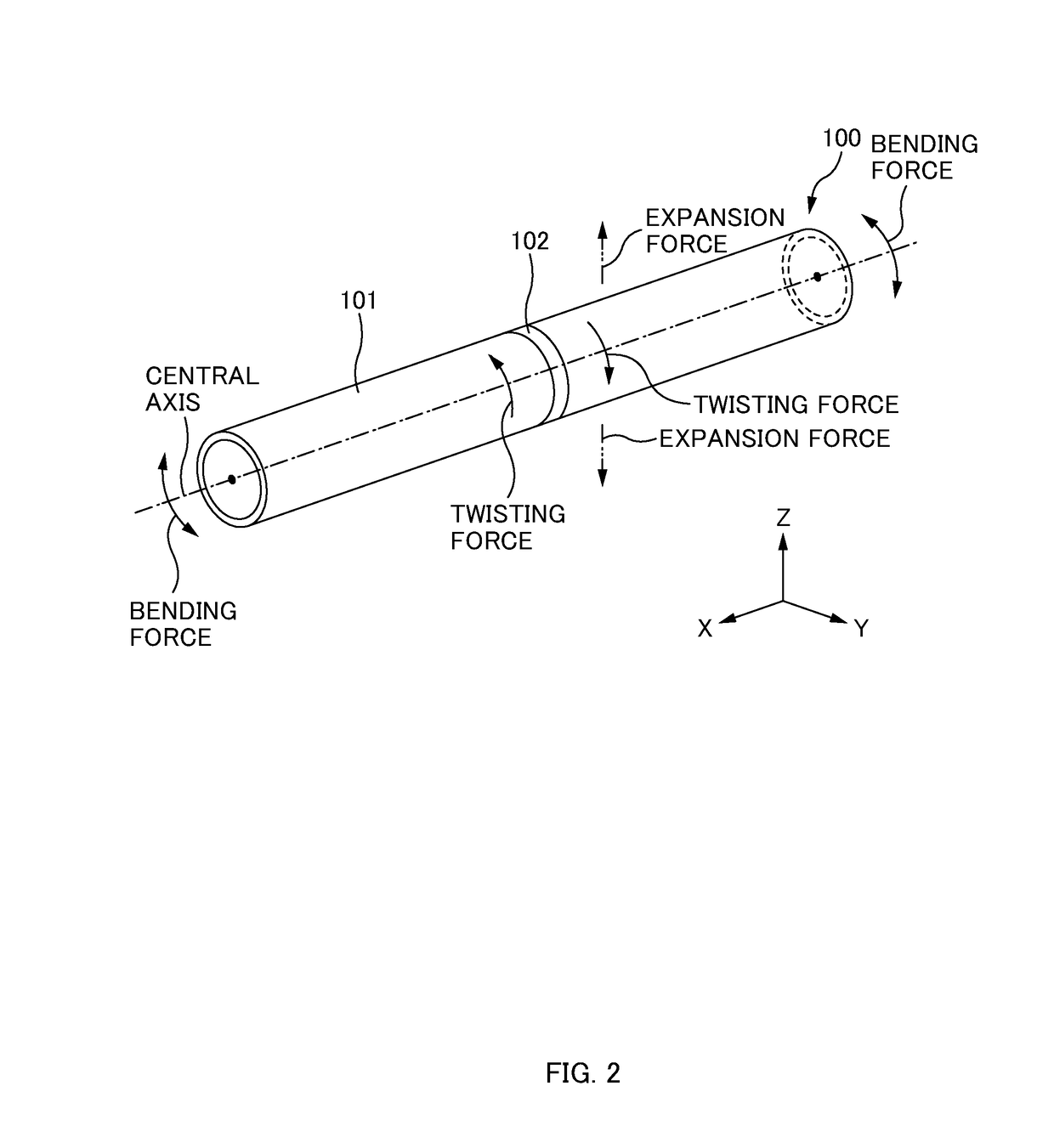
[0043]FIG. 2 is a perspective view illustrating an example of thermal stress and a straight portion of the boiler tube according to a first embodiment. FIG. 3 is a perspective view illustrating an example when a steel strip is wound on a weld portion according to the first embodiment. FIG. 4 is a perspective view illustrating an example of a state where the steel strip has been wound on the weld portion according to the first embodiment. FIG. 5 is a cross-sectional view illustrating an example of an XZ cross-section of the steel strip according to the first embodiment. FIG. 6 is an exploded perspective view illustrating a state before a reinforcement member according to the first embodiment is mounted to the straight portion of the boiler tube. FIG. 7 is a plan view illustrating a state before the reinforcement member according to the first embodiment is mounted to the straight portion of the boiler tube. FIG. 8 is a perspective view illustrating a state after the re...

Example

Second Embodiment

[0060]FIG. 11 is a perspective view illustrating an example of thermal stress and an elbow portion of a boiler tube according to a second embodiment. FIG. 12 is a perspective view illustrating an example when a steel strip is wound on a weld portion according to the second embodiment. FIG. 13 is a perspective view illustrating an example of a state where the steel strip has been wound on the weld portion according to the second embodiment. FIG. 14 is an exploded perspective view illustrating a state before a reinforcement member according to the second embodiment is mounted to the elbow portion of the boiler tube. FIG. 15 is a plan view illustrating a state before the reinforcement member according to the second embodiment is mounted to the elbow portion of the boiler tube. FIG. 16 is a perspective view illustrating a state after the reinforcement member according to the second embodiment has been mounted to the elbow portion of the boiler tube. FIG. 17 is a plan vi...

Example

Third Embodiment

[0076]FIG. 20 is a perspective view illustrating an example of a state where a steel strip has been wound on a weld portion according to a third embodiment of the present disclosure. FIG. 21 is a plan view illustrating an example of a reinforcement steel plate according to the third embodiment. FIG. 22 is a perspective view illustrating an example when the reinforcement steel plate according to the third embodiment is wrapped over the steel strip. FIG. 23 is a perspective view illustrating an example of a state where the reinforcement steel plate according to the third embodiment has been wrapped. FIG. 24 is an exploded perspective view illustrating a state before the reinforcement member according to the third embodiment is mounted to a straight portion of a boiler tube. FIG. 25 is a plan view illustrating a state before the reinforcement member according to the third embodiment is mounted to a straight portion 301 of the boiler tube.

[0077]Hereinafter, the reinforce...


PUM


Abstract

A boiler tube reinforcement device reinforces a boiler tube including a weld portion. The reinforcement device includes: a strip-shaped first steel plate that is wound and fixed by welding in a region including the weld portion of the boiler tube; a first reinforcement member in surface contact with an outer peripheral surface corresponding to one semi-circumference of the boiler tube in an outer peripheral surface of the first steel plate wound around the boiler tube; a second reinforcement member in surface contact with an outer peripheral surface corresponding to another semi-circumference of the boiler tube in the outer peripheral surface of the first steel plate wound around the boiler tube, wherein the second reinforcement member covers the outer peripheral surface of the first steel plate together with the first reinforcement member; and a coupling member that couples the first reinforcement member and the second reinforcement member together around the boiler tube.

Description

TECHNICAL FIELD[0001]The present disclosure relates to a boiler tube reinforcement device and a boiler tube reinforcement method.BACKGROUND ART[0002]For example, a boiler for power generation that is installed in a thermal power plant to rotate a turbine includes: an economizer that preheats boiler feed water; a water-cooled wall that forms a housing of the boiler and converts the boiler feed water into saturated steam; a superheater that further heats the saturated steam to be converted into superheated steam; a reheater that reheats steam from the turbine to be supplied to the turbine again; pipes that guide steam from the superheater and reheater to the turbine; and the like. The above pipes that guide steam from the superheater and reheater to the steam turbine are constituted by boiler tubes made of heat-resistant steel (for example, low-alloy steel). When the boiler for power generation is activated, high temperature and high pressure steam flows through the boiler tubes, and ...

Claims


Application Information

Patent Timeline
IPC IPC(8): F22B37/10F16L57/02
CPCF22B37/108B23K2101/06F16L57/02B23K2201/06F22B37/10F16L58/16F22B37/107F22B37/20F16L13/04
Inventor MATSUMURA, HIDEONISHIDA, HIDETAKA
Owner THE CHUGOKU ELECTRIC POWER CO INC
Why Eureka
Try Eureka