However, these approaches are inadequate because they do not account for the loss of speed in flight caused by the arrow's drag and / or they are difficult and tedious to complete.
Further, differences in arrow drag are difficult to estimate and can only roughly approximate the effects on an arrow's trajectory.
The preceding can result in significant differences in a point-of-
impact on a target (i.e., decreasing accuracy), especially for longer distance shots.
However, regardless of the specific means of adjustment, these approaches require accurate shooting to establish the sight-pin settings at the two known distances.
Therefore, the difficulty with such approaches is the amount of time they require to complete and the fact that long distant shots must be used for at least one of the two known-distances.
Therefore, it becomes more difficult for the archer to assess whether they are sighted-in with enough precision at that distance.
Longer shot-distances not only make it difficult to accurately sight-in they also require more space than is typically available at indoor range facilities.
Therefore, it can be difficult to locate a facility that allows the conventional sight-in procedure.
The preceding challenges also arise where a multi-pin sight is used because long distance shots must also be taken.
Thus, the sight pin setting at 40, 50 or more yards results in the above drawbacks of shooting a long distance during the sight-in process.
However, these
software programs suffer from many of the same drawbacks because they also require that the archer sight-in at multiple distances including at least one distance of 50 yards or more.
However, estimated arrow drag often results in an imprecise value.
However, current approaches are crude and lack precision.
However, this approach is imprecise, is provided in a
low resolution format and provides a result in a form that makes it difficult to directly transfer to an archery sight.
Further, even the manner in which the indicia are provided can limit their effectiveness.
As a result, the approach does not allow the user any mobility, for example, the ability to go to an outside archery range where
electricity is unavailable and try the effects of various equipment adjustments on their sight settings.
These approaches are also tedious and inflexible because the user cannot easily determine how a change in one or more parameters (for example, overall arrow weight, arrow
weight distribution sometimes referred to as front-of-center, arrow launch speed, arrow drag, etc.) effects the location of the sight marks relative to one another.
In particular, the approach does not provide any ability to see the effects of changes in equipment performance on archery sight settings as the changes are made.
However, electronic archery sights are not legal in many states.
Also, electronic sights can easily be damaged in the field by shock and / or
moisture.
Once power is lost the sight becomes inoperative.
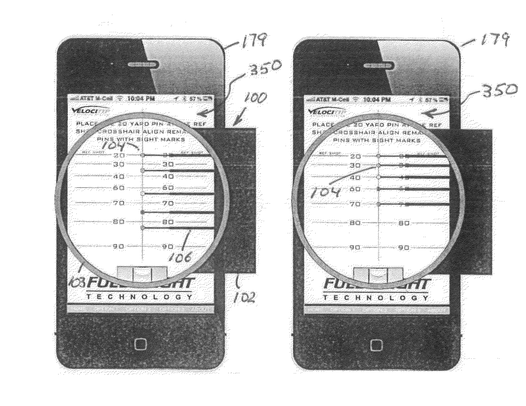
However, neither the '273 patent nor any other prior approach describes how to utilize a portable electronic device with any style of display to generate a set of sight marks in a manner that allows the sight marks to be easily transferred from a graphical
user interface to an archery sight, in particular, to an archery sight that includes one or more sight-pins whose location in the sight housing is mechanically adjusted.

