Image transforming vision enhancement device

a technology of enhancement device and image, which is applied in image enhancement, color signal processing circuit, instruments, etc., can solve the problems of limited digital processing of images, reduced visibility, and limited specific color filtering provided by individually configured lenses, so as to reduce glare, brighten dark areas of images, and reduce glare.

Active Publication Date: 2016-09-13
DIGITAL VISION ENHANCEMENT
View PDF19 Cites 11 Cited by
  • Summary
  • Abstract
  • Description
  • Claims
  • Application Information

AI Technical Summary

Benefits of technology

[0016]Embodiments of the invention provide vision enhancement capabilities to assist colorblind users. Such users have difficulty distinguishing between certain colors. The image transformation functions of these embodiments may map colors that are difficult or impossible for a colorblind user to distinguish into different colors that such a user can easily distinguish. For example, the brightness of colors may be selectively altered to make color differences more apparent. As opposed to the typically used technique to correct colorblindness by providing an analog colored filter in one lens of a pair of glasses, which has the effect of making overall images darker, one or more embodiments of the invention may for example use the opposite technique of adding brightness in selected wavelengths to assist with color differentiation. This technique of adding brightness is not possible in the analog filters of the prior art because analog filters can only remove or attenuate light in selected wavelengths. Embodiments that add brightness to selectively provide significant benefits over the inherently subtractive filters in the prior art, because the overall brightness of an image may be preserved or enhanced.
[0018]One or more embodiments of the invention modify the brightness of selected pixels, in order to improve visibility of dark scenes or regions, or to reduce excessive brightness or glare of overly bright pixels or regions, or both. Such embodiments may assist with nighttime or low-light vision. An example application is an embodiment that darkens colors above a certain level of brightness in order to reduce glare from headlights of oncoming or following cars. In some embodiments the image transformation could both darken excessively bright pixels and brighten excessively dark pixels; this combined effect provides additional advantages for nighttime driving where excessive glare and poor visibility in darkness are both potential problems. Such an embodiment may for example be embedded in driving glasses, or into the windshield or rear-view mirror or other component of a car or other moving vehicle.
[0019]One or more embodiments provide capabilities that allow users to see light frequencies outside the human visible frequency range. Cameras in these embodiments may capture frequencies such as infrared or ultraviolet, or any other electromagnetic frequency such as gamma rays, x-rays, microwave, or radio waves. Any sensor that can capture any range or any set of ranges of the electromagnetic spectrum may be used as a camera in embodiments of the invention. In embodiments that capture non-visible frequencies, the image transformation functions of these embodiments may map these invisible frequencies into visible frequencies for display. Illustrative applications for such embodiments may include for example visualizing heat losses, monitoring radiation levels for safety, searching for hidden transmitters and hidden listening or recording devices, and configuring and optimizing wireless networks. Various techniques may be used to map invisible frequencies into the visible frequency range. In some embodiments, the image transformation function partitions the display color space into two subspaces: one subspace is used to represent visible frequencies, and the other is used to represent invisible frequencies. For example, if the display color space is RGB, then the red component may be used to represent invisible (such as infrared) frequencies, and the green and blue components may be used to represent visible frequencies. Some embodiments simply discard certain visible frequency information and use the remaining visible spectrum to represent invisible frequencies. Some embodiments instead compress the visible frequency range rather than discarding portions of it. For example, in one or more embodiments the camera color space and display color space may be HSV (hue-saturation-value) or some similar color space. In these embodiments the hues of visible frequencies are typically represented as angles within the range 0 to 360. This range of 0 to 360 may be compressed, for example to the range 0 to 240, leaving a range of hues for representation of invisible frequencies like infrared. Embodiments using visible frequency compression provide the benefit that distinct colors are typically mapped to distinct colors, although the differences between colors may be reduced.
[0020]One or more embodiments may combine visible frequencies and invisible frequencies onto one or more displays. For example in an embodiment with a left eye display and a right eye display, one display may show visible frequencies, and the other display may show invisible frequencies (where these invisible frequencies are transformed into visible frequencies using any desired transformation function). In another embodiment, invisible frequencies may be shown in a picture-in-picture display inserted into or beside an image showing visible frequencies. In another embodiment, one or more displays may alternate between displaying visible frequencies and displaying invisible frequencies, either at a fixed rate or upon receiving input from a user to change the displayed frequency range. Any method of combining several light frequency ranges onto one or more displays is in keeping with the spirit of the invention. With these techniques embodiments of the invention may effectively broaden the range of light frequencies that are visible to a user beyond the normal range of human vision. Moreover the specific frequencies made visible to a user or emphasized in an image display may be customized to the requirements of a particular application.

Problems solved by technology

They are therefore limited to the specific color filtering provided by the individually configured lenses.
Since analog filters can only remove or attenuate light of particular wavelengths, these filters also typically darken the resulting image, which may often reduce visibility.
More recently some computer and mobile phone based systems have emerged that provide limited digital processing of images to assist colorblind users.
While the devices and techniques known in the art have proven helpful to some users, they have not provided full color vision to colorblind users.
No general-purpose digitally programmable vision enhancement device is known in the art that can provide a flexible, configurable system for altering and enhancing images.
No known system or method can alter or enhance images in multiple ways, including color transformations, addition of graphics or captions, magnifying images, or generating images that vary over time.
No known systems provide flexible transformation and augmentation of images in the visible spectrum along with display of invisible frequencies such as infrared or ultraviolet.
No known systems integrate such general and flexible image transformations into a vision enhancement device that can be embedded in glasses, contact lenses, binoculars, or other vision devices.

Method used


Image

  • Image transforming vision enhancement device
  • Image transforming vision enhancement device
  • Image transforming vision enhancement device

Examples


Embodiment Construction

[0046]An image transforming vision enhancement device will now be described. In the following exemplary description numerous specific details are set forth in order to provide a more thorough understanding of embodiments of the invention. It will be apparent, however, to an artisan of ordinary skill that the present invention may be practiced without incorporating all aspects of the specific details described herein. In other instances, specific features, quantities, or measurements well known to those of ordinary skill in the art have not been described in detail so as not to obscure the invention. Readers should note that although examples of the invention are set forth herein, the claims, and the full scope of any equivalents, are what define the metes and bounds of the invention.

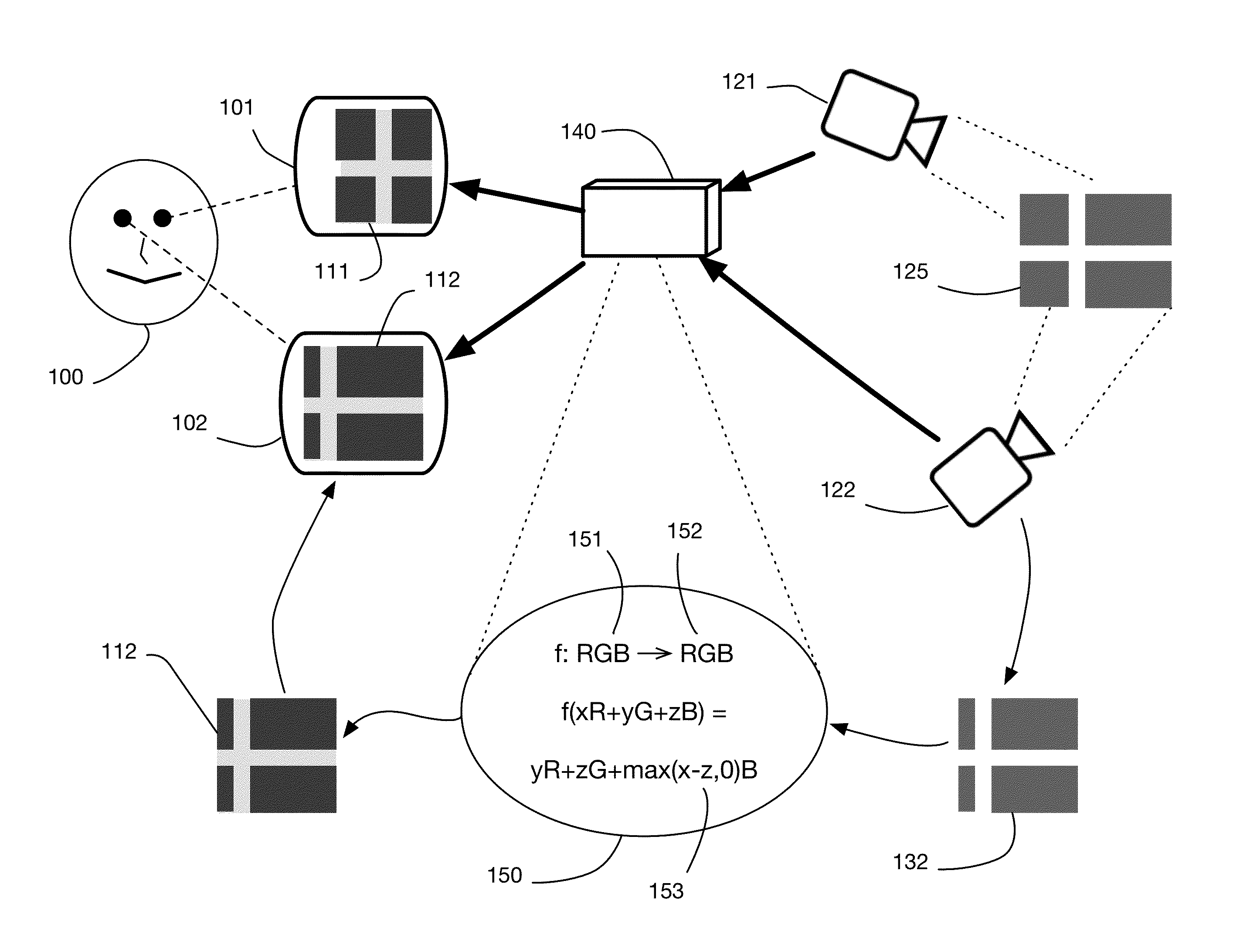
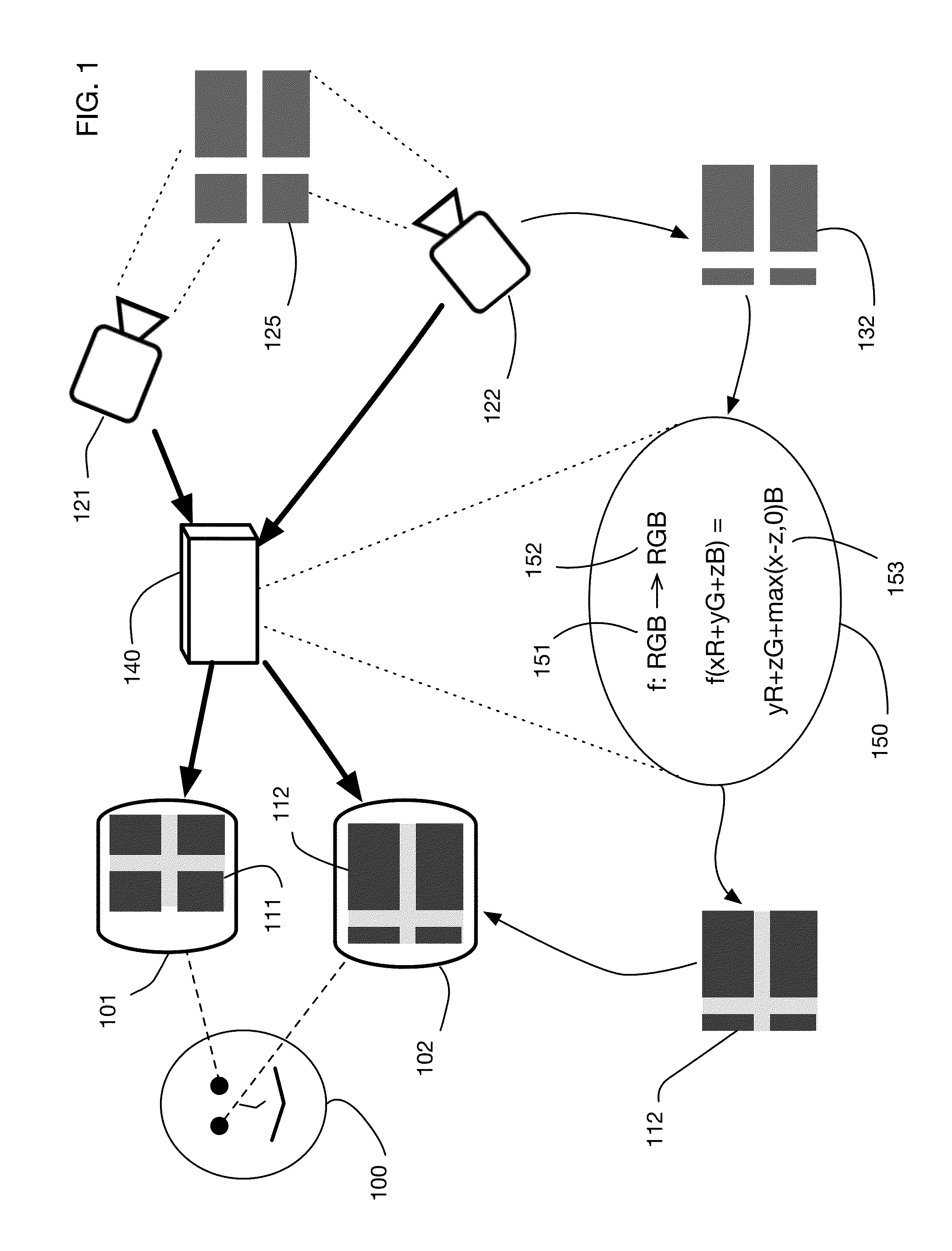
[0047]FIG. 1 shows an architectural view of an embodiment of an image transforming vision enhancement device. User 100 is depicted using the device, although in some embodiments multiple users may use th...


PUM


Abstract

Image transforming vision enhancement device that enhances vision by transforming images provided by one or more cameras into modified images projected on one or more displays. The system may be embedded in glasses, contact lenses, binoculars, or other vision devices, in computer screens, or in components of moving vehicles. Image transformations may include modifying colors to assist colorblind users or to highlight color ranges, mapping invisible frequencies into visible colors, adding labels or graphics, and generating time-varying images with flashing or changing features. Images from multiple cameras may be combined, providing users with panoramic vision from a single device. Low light vision may be enhanced, and excessive glare may be attenuated. The system may magnify images with a variable magnification. User interfaces may be provided to configure and customize the image transformations.

Description

[0001]This utility patent application claims the benefit of U.S. Provisional Patent Application No. 62 / 122,130, filed 14 Oct. 2014, the specification of which is hereby incorporated herein by reference.BACKGROUND OF THE INVENTION[0002]1. Field of the Invention[0003]This invention relates generally to the field of correction, augmentation, and enhancement of vision. In particular, but not by way of limitation, one or more embodiments of the invention relate to an image transforming vision enhancement device, for example that may be utilized to transform images using color transformations and mapping, magnification, cropping, rotation, scaling, selection, and overlay of graphics or labels and generating time-varying images with flashing or changing features to indicate colors for example, or any combination thereof.[0004]2. Description of the Related Art[0005]Vision enhancement devices such as specialized eyeglasses or contact lenses are known in the art. In particular, eyeglasses to ...

Claims


Application Information

Patent Timeline
Patent Type & Authority Patents(United States)
IPC IPC(8): H04N7/18G06T5/20H04N5/225H04N9/04H04N13/04G09G5/02G06T11/00
CPCG09G5/02G06T5/20G06T11/001H04N5/2253H04N9/04H04N13/0422G06T2207/10024G09G2340/06G09G3/001G09G3/002G09G3/003G09G2340/12G09G2370/022H04N5/272H04N9/67H04N13/257H04N13/239H04N23/63H04N23/11H04N13/324H04N23/54G02C11/10
Inventor BORENSTEIN, NATHANIEL S.NEUENDORFFER, THOMAS P.
Owner DIGITAL VISION ENHANCEMENT
Why Eureka
Try Eureka