Eureka AIR delivers breakthrough ideas for toughest innovation challenges, trusted by R&D personnel around the world.

Modular redundant power supply

a power supply and module technology, applied in the direction of electrical apparatus construction details, instruments, support structure mounting, etc., can solve the problems of power integration panel still having malfunction risk, power regulation function of power integration panel fixed and cannot be changed according, and power loss could occur

Inactive Publication Date: 2016-09-20
ZIPPY TECH
View PDF23 Cites 12 Cited by
  • Summary
  • Abstract
  • Description
  • Claims
  • Application Information

AI Technical Summary

Benefits of technology

The present invention provides a modular redundant power supply with a removable power regulation module that can adjust according to actual requirements. This solves the problem of difficulty in repairs and maintenance of conventional redundant power supplies. The power regulation module can be selected based on actual requirements, and the power supply modules are easily installed and removable. The power regulation module has a power connection end that receives power from the integrated circuit and outputs it to the external device through an auxiliary duty power. The power integration panel and power supply modules have flexible installation options, and the power regulation module can adjust the output power according to requirements.

Problems solved by technology

However, in practice during power supply operation of the redundant power supply the power integration panel still has malfunction risk.
In addition, once the redundant power supply is finished in production the power regulation function of the power integration panel is fixed and cannot be changed according to actual implementation requirements.
Hence the problem of power loss could take place.

Method used


Image

  • Modular redundant power supply
  • Modular redundant power supply
  • Modular redundant power supply

Examples


Embodiment Construction

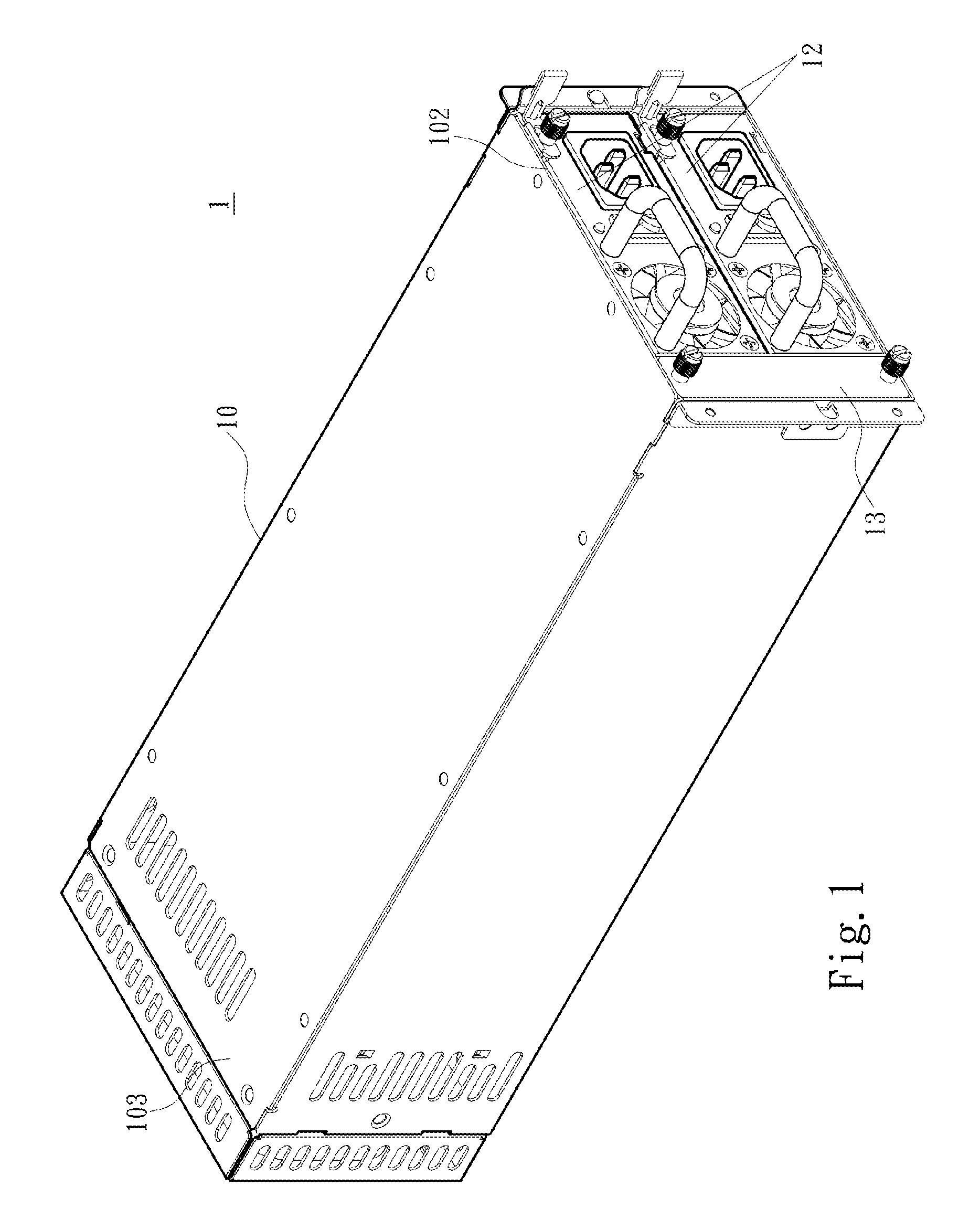
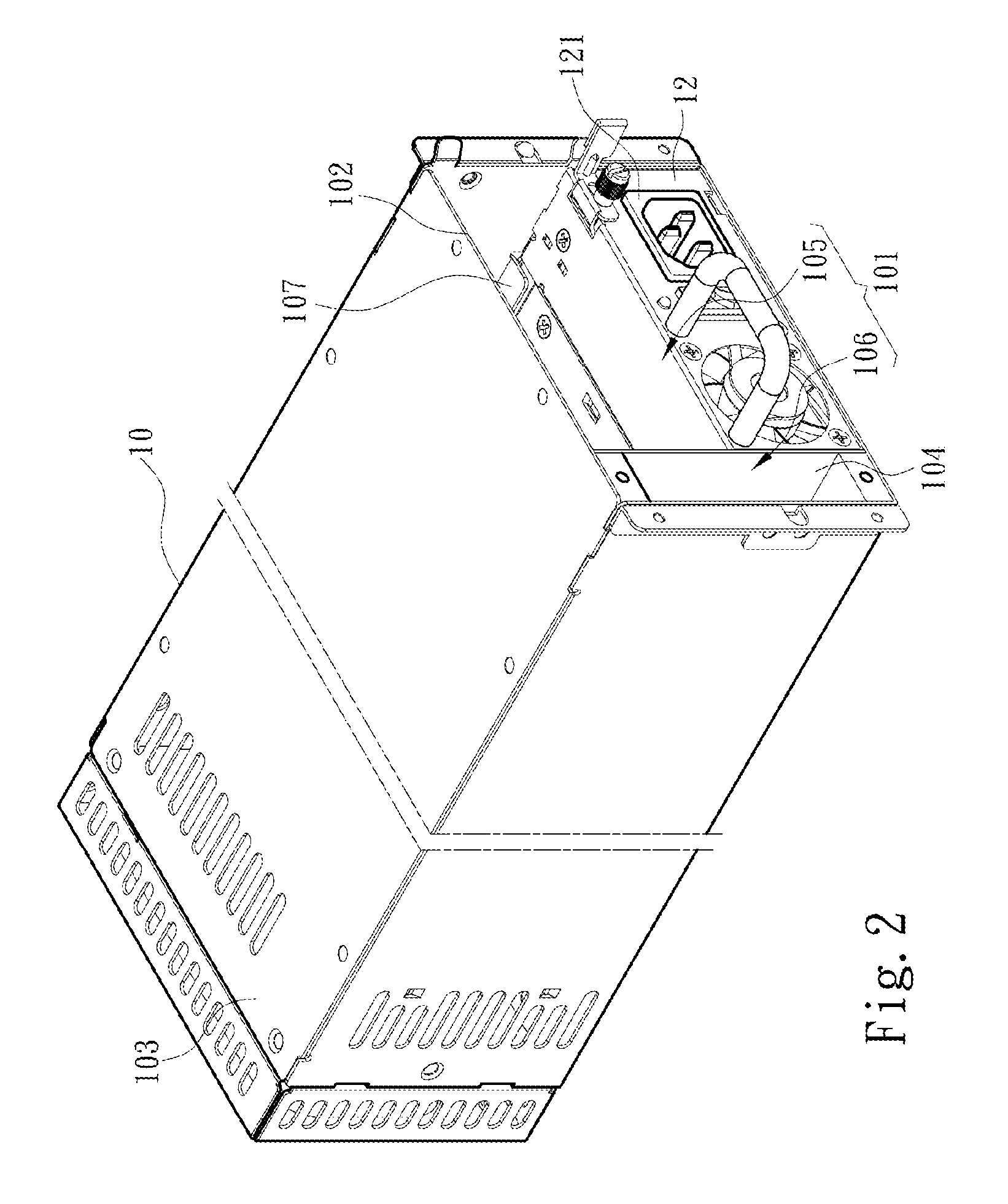
[0019]Please referring to FIGS. 1 through 4, the present invention aims to provide a modular redundant power supply that includes a casing 10, a power integration panel 11, a plurality of power supply modules 12 and a power regulation module 13. In one embodiment the casing 10 can be made via mechanical fabrication processes such as stamping a metallic material and the like. The finished casing 10 has an installation space 101 with an open side formed an installation opening 102 and an installation distal end 103 at a closed another side opposing the installation opening 102. The casing 10 also has at least one installation aperture (not shown in the drawings) at the installation distal end 103 for wiring of electronic elements located in the installation space 101 to connect to an external device 2. The casing 10 further has an assembly rack 104 located in installation space 101 to define a first installation zone 105 and a second installation zone 106. In addition, by adjusting th...


PUM


Abstract

A modular redundant power supply includes a casing, a power integration panel, a plurality of power supply modules and a power regulation module. The casing has an installation space defined into a first installation zone and a second installation zone. The power integration panel is located in the installation space. The power supply modules are installed on the first installation zone and connected to the power integration panel. Each power supply module outputs a duty power to the power integration panel after being started. The power regulation module gets the duty power from the power integration panel and regulates thereof to generate an auxiliary duty power output to the power integration panel so that the power integration panel can supply the duty power and the auxiliary duty power to an external device.

Description

FIELD OF THE INVENTION[0001]The present invention relates to a redundant power supply and particularly to a modular redundant power supply.BACKGROUND OF THE INVENTION[0002]Technology industry at present usually has high demand on power supply stability. To meet this end a redundant power supply has been developed. The redundant power supply mainly includes a primary power supply, a secondary power supply for backup and a power integration panel. When power supply is started the power integration panel receives electric power output from the primary power supply and the secondary power supply to supply to a load. The power integration panel also regulates the received power to generate a voltage required in operation of motherboards.[0003]Moreover, in order to facilitate fast repairs and maintenance of the primary power supply or the secondary power supply the conventional redundant power supply generally has the power integration panel located at a distal end of a casing to make loa...

Claims


Application Information

Patent Timeline
Patent Type & Authority Patents(United States)
IPC IPC(8): G06F1/18H05K7/14H05K7/10
CPCH05K7/10H05K7/1492H05K7/1457G06F1/188G06F1/263
Inventor SHIH, TSUN-TECHANG, YU-YUANCHANG, HENG-CHIASU, CHUN-LUNG
Owner ZIPPY TECH
Why Eureka
Eureka Blog
Learn More