Metal-to-metal seal with wiper element and wellhead system incorporating same

a technology of wiper element and seal, which is applied in the direction of sealing/packing, mechanical equipment, borehole/well accessories, etc., can solve the problems of less robustness in the general seal, less robustness in the seal, and difficulty in maintaining a seal, so as to improve the sealing and wiping of any surface defects, increase the robustness of the seal assembly, and improve the effect of sealing and wiping

Inactive Publication Date: 2013-03-12
VETCO GRAY
View PDF24 Cites 17 Cited by
  • Summary
  • Abstract
  • Description
  • Claims
  • Application Information

AI Technical Summary

Benefits of technology

[0006]In an embodiment of the present technique, a seal assembly is provided that comprises two U-shaped seals that form a metal-to-metal seal and has features that increase the robustness of the seal assembly in the event surface degradation or defects in a bore of an outer wellhead or treehead member increases the difficulty of maintaining a seal. The seal assembly also has an elastomeric wiper element formed between the two seals that could wipe the bore of the outer wellhead member of debris during installation of the seal assembly. The wiping effect is applicable if the seal assembly is pressurized from above when at its final landed position. The elastomer wiping element also provides additional support for the legs of the two U-shaped seals and can provide additional radial energization for the seal assembly.
[0007]In an illustrated embodiment, wedges can be forced into the u-shaped pocket of each of the seals to create a metal-to-metal seal between the tips of the legs and the wellhead member surfaces. The wedges may also be wiping elements. The wedges / wiper further energize the elastomer radially to improve sealing and wiping of any surface defects on the bore of the outer wellhead member. Alternatively, a soft metallic material could be used in place of the elastomer in the wiping element that could additionally fill minor surface defects. The seal assembly is preferably pre-assembled onto an inner wellhead member, such as a casing hanger or tubing hanger. The casing hanger or tubing hanger and seal assembly may then be lowered into an outer wellhead member, such as a wellhead housing or treehead, in the same run and the seal set with a conventional running tool.
[0008]In an illustrated embodiment, a cavity may also be formed between the two U-shaped seals. The cavity may be filled with a soft metal or intercalated graphite compound that flows outward and inward in response to applied pressure and / or temperature. The soft metal or intercalated graphite can wipe into surface defects to effectively repair them.
[0009]The pocket formed by the legs of each of the U-shaped seals may remain empty to allow well pressure to act on the inner side of the legs, pushing the legs outward against the outer and inner wellhead members. This embodiment would not require the use of a wedge to force the legs outward into sealing contact with the outer and inner wellhead or treehead members.
[0010]The seal assembly can rest on a shoulder formed on the wellhead housing or tubing hanger and can be set by a conventional running tool that can push the seal assembly into place. Alternatively, the seal assembly could be set by pressurizing the annular space between the outer and inner wellhead or treehead members. The combination of the wiping element, the robustness added to the U-shaped seals by the wiping element that joins them, and the radial energization of the wiping element improves sealing in wellhead or treehead members having surface degradations.

Problems solved by technology

If the bore or surface of the outer wellhead or treehead member is damaged, a seal would struggle to maintain a seal.
However, the elastomeric portion of the seal assembly may not have sufficient radial energization and may result in leakage, sub-optimal wiping, and less robustness in the seal in general.

Method used


Image

  • Metal-to-metal seal with wiper element and wellhead system incorporating same
  • Metal-to-metal seal with wiper element and wellhead system incorporating same
  • Metal-to-metal seal with wiper element and wellhead system incorporating same

Examples


Embodiment Construction

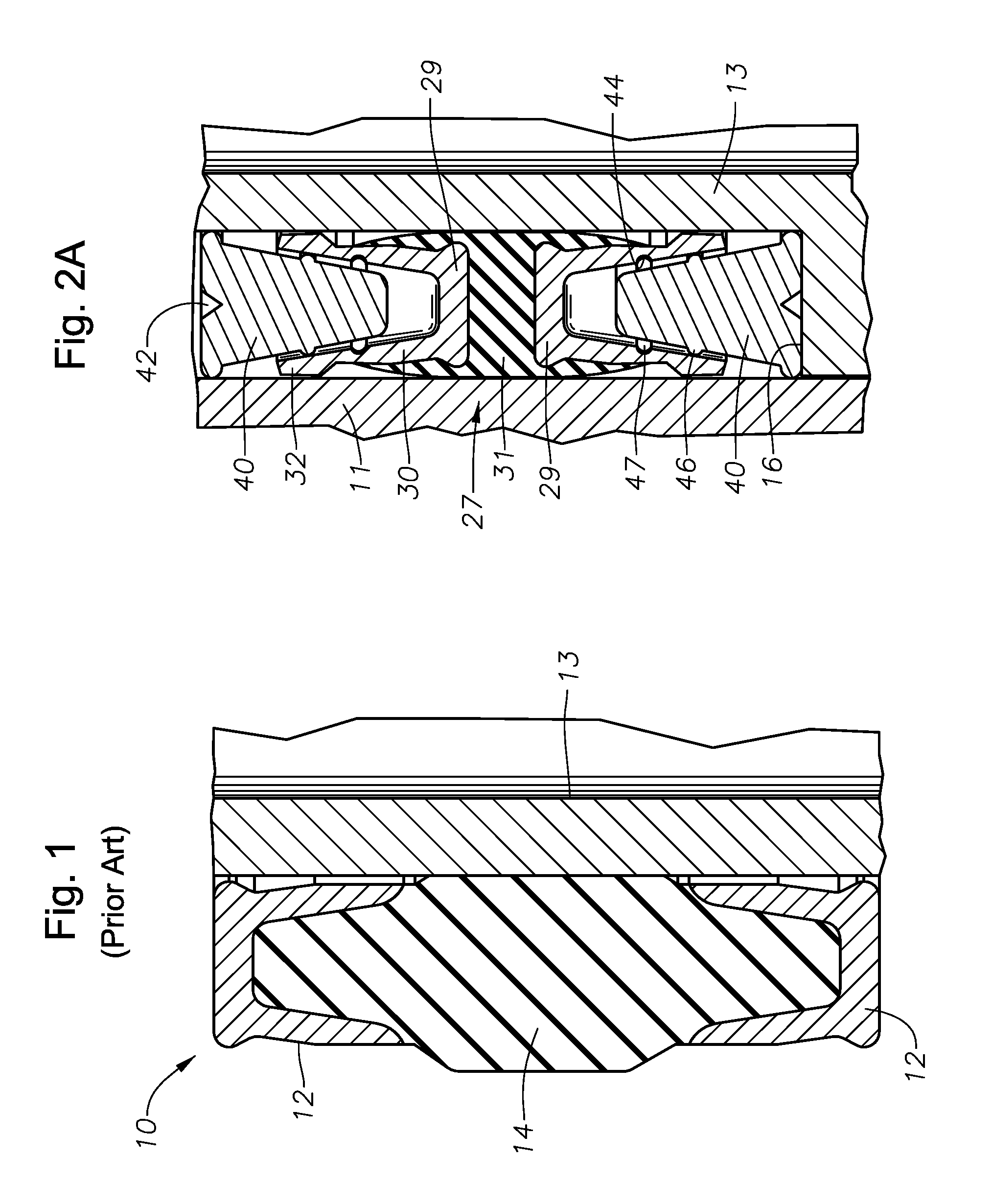
[0017]Referring to FIG. 1, a seal assembly 10 of the prior art is shown located between an outer wellhead or treehead member 11 and an inner wellhead or treehead member 13. Upper and lower metallic rings 12 each have a concave shape with legs that face each other. An elastomeric seal section 14 fits in the concave space of each metallic ring 12 and bulges outward for sealing against an outer wellhead member. The bulging portion of elastomeric seal section 14 deforms against the outer wellhead member, forcing an inner side of elastomeric seal section 14 in sealing engagement with an inner wellhead housing member. Portions of rings 12 sealingly engage the inner and outer wellhead members. This engagement may be induced from elastomeric energization.

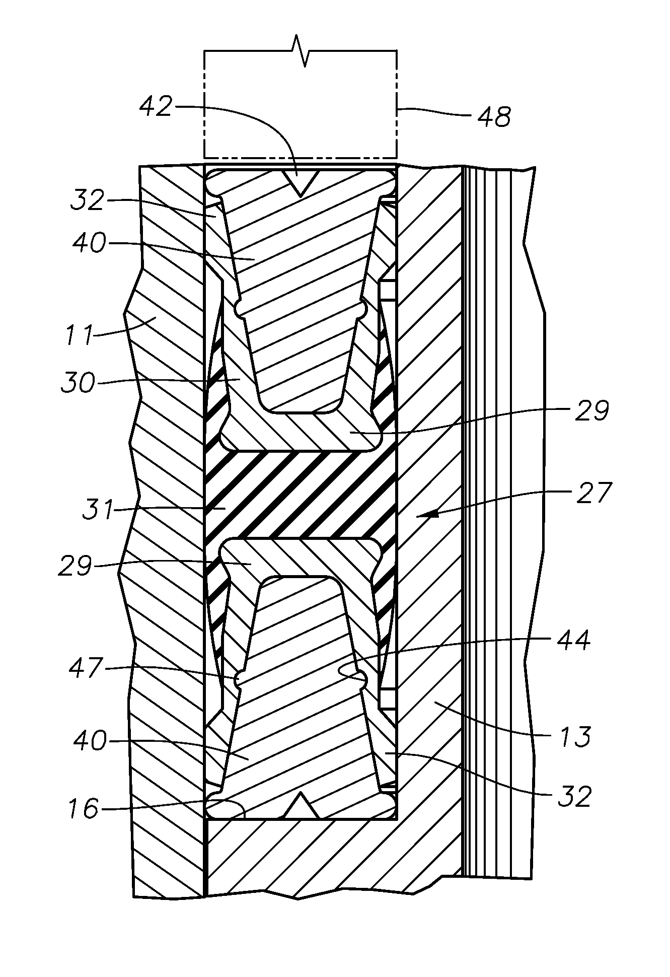
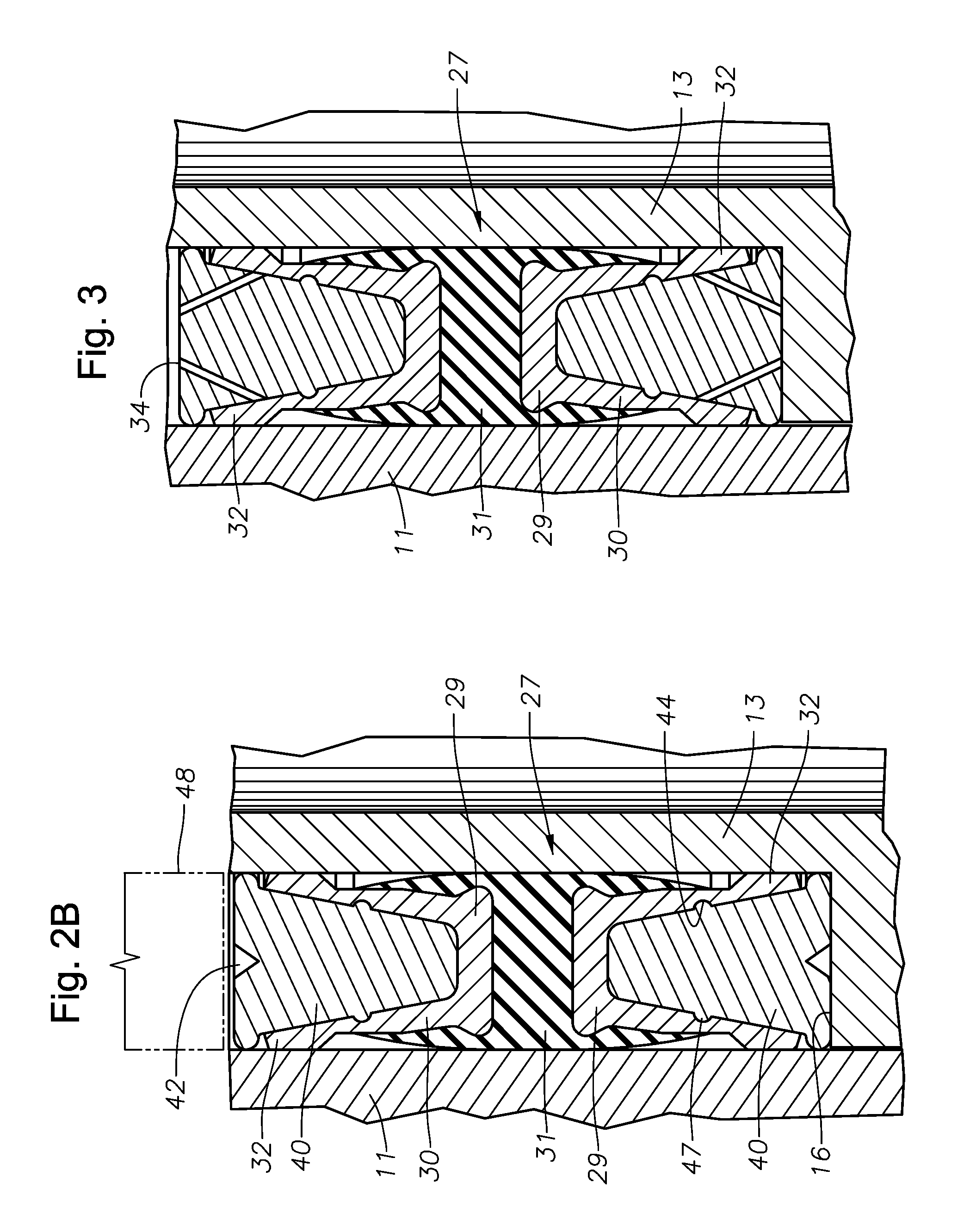
[0018]Referring to FIG. 2A an embodiment of the invention shows a portion of an inner wellhead or treehead member that comprises a casing hanger 13 having an outer profile and a radially extending shoulder 16. Alternatively, casing hanger 1...


PUM


Abstract

A wellhead or Christmas tree seal assembly that forms a metal-to-metal seal between inner and outer wellhead or Christmas tree members. U-shaped metal seals having legs that face in opposite directions, are bonded to a wiping element. During installation of the seal assembly, the ends of the seal legs seal against the wellhead members and the wiping element compensates for defects on the surfaces of the wellhead members. The wiping element can be of an elastomer, metallic, or intercalated graphite material.

Description

FIELD OF THE INVENTION[0001]This invention relates in general to subsea Christmas trees and wellhead assemblies and in particular to a seal for sealing between inner and outer wellhead members or between a Christmas tree and tubing hanger.BACKGROUND OF THE INVENTION[0002]Seals are used between inner and outer wellhead tubular and / or tree head members to contain internal well pressure. The inner wellhead member may be a casing hanger located in a wellhead housing and that supports a string of casing extending into the well. A seal or packoff seals between the casing hanger and the wellhead housing. Alternatively, the inner wellhead member could be a tubing hanger that supports a string of tubing extending into the well for the flow of production fluid. The tubing hanger lands in an outer wellhead member, which may be a wellhead housing, a Christmas tree, or a tubing head. A packoff or seal, seals between the tubing hanger and the outer wellhead member.[0003]A variety of seals of this...

Claims


Application Information

Patent Timeline
Patent Type & Authority Patents(United States)
IPC IPC(8): E21B33/02F16J15/10
CPCE21B33/04E21B2033/005E21B2200/01F16J15/121
Inventor BUCKLE, KEVIN G.
Owner VETCO GRAY
Why Eureka
Try Eureka