Modeling method for substation-dispatching center two-level distributed type power grid

A technology of distributed power grid and dispatch center, applied in electrical digital data processing, instruments, computer-aided design, etc., can solve the problems of unable to achieve self-healing of models, topology errors, increased workload, etc., to reduce maintenance workload and errors efficiency, small modeling scale, and simple maintenance

Active Publication Date: 2012-06-27
TSINGHUA UNIV +1
View PDF4 Cites 18 Cited by
  • Summary
  • Abstract
  • Description
  • Claims
  • Application Information

AI Technical Summary

Problems solved by technology

[0004] The main problems of this centralized method are as follows: (1) The establishment of the grid model of the whole network (including equipment parameters, static topology, and primary wiring diagram) must be completed in the dispatching center, and the workload increases with the increasing scale of the grid. A significant increase
(2) It is impossible for the maintenance personnel in the dispatch center to be very familiar with every detail of the power grid, and the potential for errors is very high. Such parameter errors or topology errors will be lost in the huge power grid model information, making it difficult to locate
(3) Under the current centralized modeling method, if the dispatch center is hit by a disaster, it will easily lead to the paralysis of all functions, and it is difficult to heal itself
This method has the following deficiencies: (1) The splicing is the model under the jurisdiction of different dispatch centers, and the boundary is the boundary equipment between the jurisdiction areas of each dispatch center; it does not consider the more basic splicing model of the substation into the dispatch center model
(2) This method still needs to be modeled in the dispatch center
(3) There is a problem with the dispatch center model, and this method cannot realize the self-healing of the model
(4) This method does not consider the splicing of graphics and real-time data

Method used


Image

  • Modeling method for substation-dispatching center two-level distributed type power grid
  • Modeling method for substation-dispatching center two-level distributed type power grid
  • Modeling method for substation-dispatching center two-level distributed type power grid

Examples


Embodiment Construction

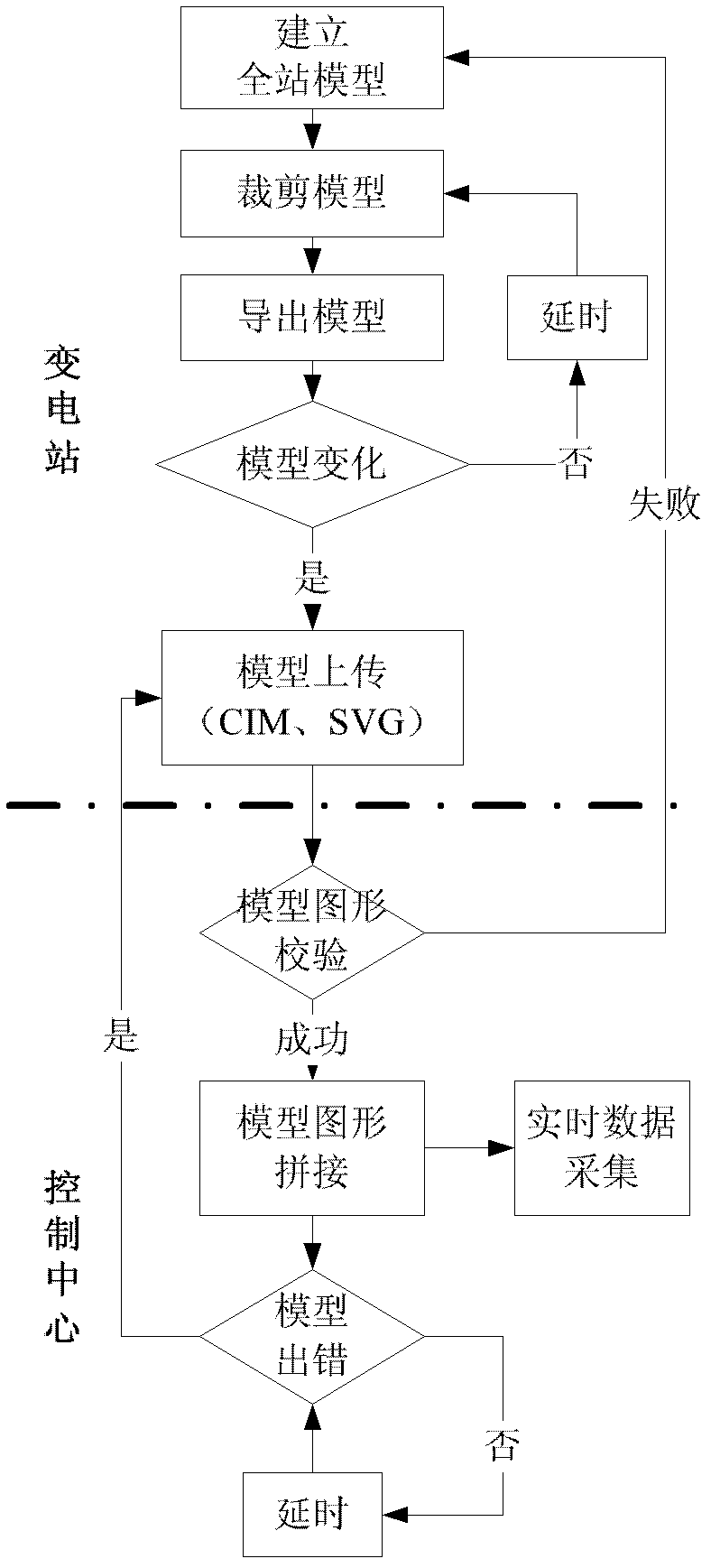
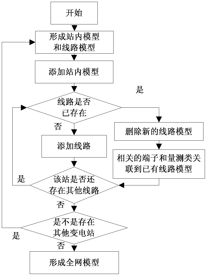
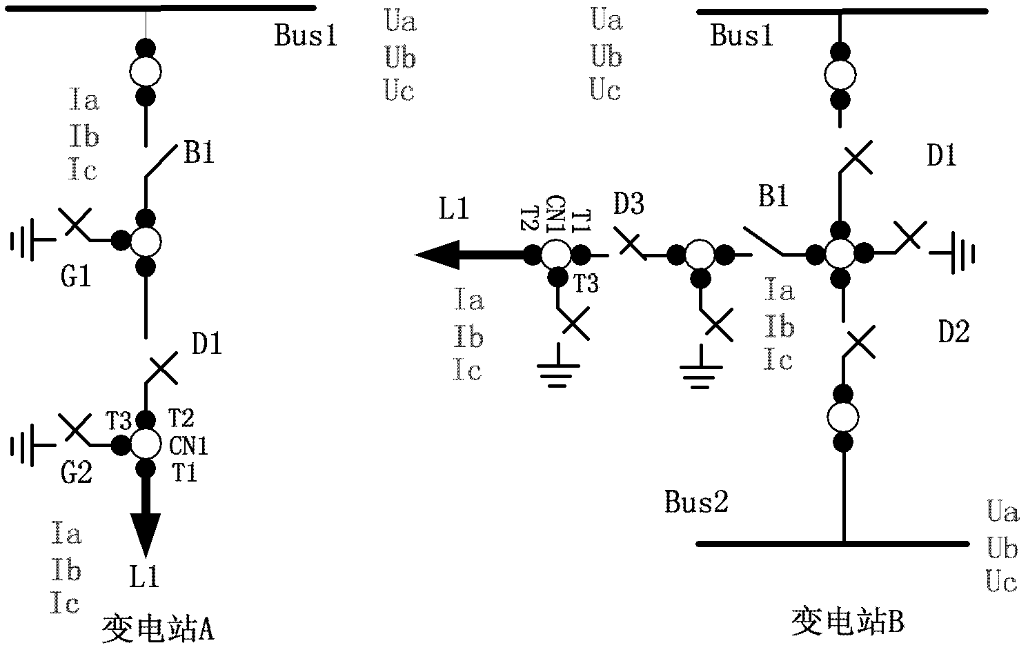
[0032] The modeling method of the substation-dispatching center two-level distributed power grid proposed by the present invention is described as follows in conjunction with the accompanying drawings and the description of the embodiments:

[0033] The present invention proposes a method for modeling a substation-dispatching center two-level distributed power grid, which is characterized in that the method includes: locally establishing a network model ( ) and wiring in each substation that includes topology, equipment parameters, and measurement information Diagram, used for local monitoring, analysis and calculation of the substation, and automatically derives the substation model and wiring diagram suitable for the dispatch center, and transmits it to the dispatch center through the power dispatch data network (SPDnet); at the dispatch center level, the global consistency based on the line identification The network model of each substation is docked and automatically splic...


PUM


Abstract

The invention relates to a modeling method for a substation-dispatching center two-level distributed type power grid, which belongs to the technical field of operation and control of an electric power system. The method includes that a network model containing a topological structure, device parameters and measuring information and a wiring scheme are built in each substation local and used for monitoring, analyzing and calculating the substation locals, and substation models and wiring schemes which are suitable for a dispatching center are led out automatically and transmitted to the dispatching center through an electric power dispatching data network; and at a dispatching center level, based on global consistency of line identification, all the substation network models are in butt joint to be automatically spliced into a global power grid model used for achieving monitoring, analysis and control of a whole network. The method achieves once modeling and whole network utilization, and provides a modeling basis for layered grading information processing and self-healing of the power grid.

Description

technical field [0001] The invention belongs to the field of power system operation and control, in particular to a modeling method for a two-stage distributed power grid of a substation-dispatch center. Background technique [0002] In the energy management system (Energy management system, EMS) architecture, it is a computer-based dispatching automation system for modern power systems. Its task is to collect, monitor, analyze, optimize and control the power system in real time. Power grid model and wiring diagram are the foundation and core link of EMS, and the basis of monitoring, analysis, optimization and control. The power grid model includes the topological structure of equipment, equipment parameters, and measurement information. The topological structure and equipment parameters of the equipment include the topology and parameters of equipment such as transformers, lines, generators, loads, switches, isolation switches, and grounding switches. The measurement info...

Claims


Application Information

Patent Timeline
Patent Type & Authority Applications(China)
IPC IPC(8): G06F17/30G06F19/00
CPCG06F2217/78G06F17/50G06Q50/06Y02E60/76G06F17/30G06F17/5036Y04S40/22G06F30/367G06F2119/06Y02E60/00Y04S40/20
Inventor 孙宏斌葛敏辉吴文传汪德星郭庆来张伯明王晶
Owner TSINGHUA UNIV
Why Eureka
Try Eureka