Collapsible torque wrench

a torque wrench and collapsible technology, applied in the field of torque wrenches, can solve the problems of affecting the smoothness of operation, deteriorating the precision of the torque value of the wrench, and components that cannot be independently replaced, and achieve the effect of convenient replacemen

Active Publication Date: 2016-09-27
KABO TOOL COMPANY
View PDF8 Cites 5 Cited by
  • Summary
  • Abstract
  • Description
  • Claims
  • Application Information

AI Technical Summary

Benefits of technology

[0010]It is therefore a primary object of the present invention to provide a collapsible torque wrench, in which the components can be easily replaced without wasting.
[0011]It is a further object of the present invention to provide the above collapsible torque wrench, in which the components are assembled in such a manner that the components will not over-abrade each other so as to ensure the precision of the torque value of the wrench.
[0018]Accordingly, the fixing block is demountably / removably mounted in the tubular body, and can be easily replaced. The installation of the fixing block will not cause deformation of the fixing block.
[0020]Preferably, a relatively soft member is mounted in the pivot portion between the shank and the connection rod, the gap between the shank and the connection rod is minimized and the wear thereof is reduced. The precision of the torque value of the torque wrench can be ensured.

Problems solved by technology

This will affect the smoothness of operation of the mechanism and deteriorate the precision of the torque value of the wrench.
As a result, the component cannot be independently replaced.
This leads to waste of resource.
Accordingly, the poor structural design of the conventional torque wrench 10 leads to higher cost for replacement of the components and deterioration of the precision of the torque value and needs to be improved.

Method used


Image

  • Collapsible torque wrench
  • Collapsible torque wrench
  • Collapsible torque wrench

Examples


Embodiment Construction

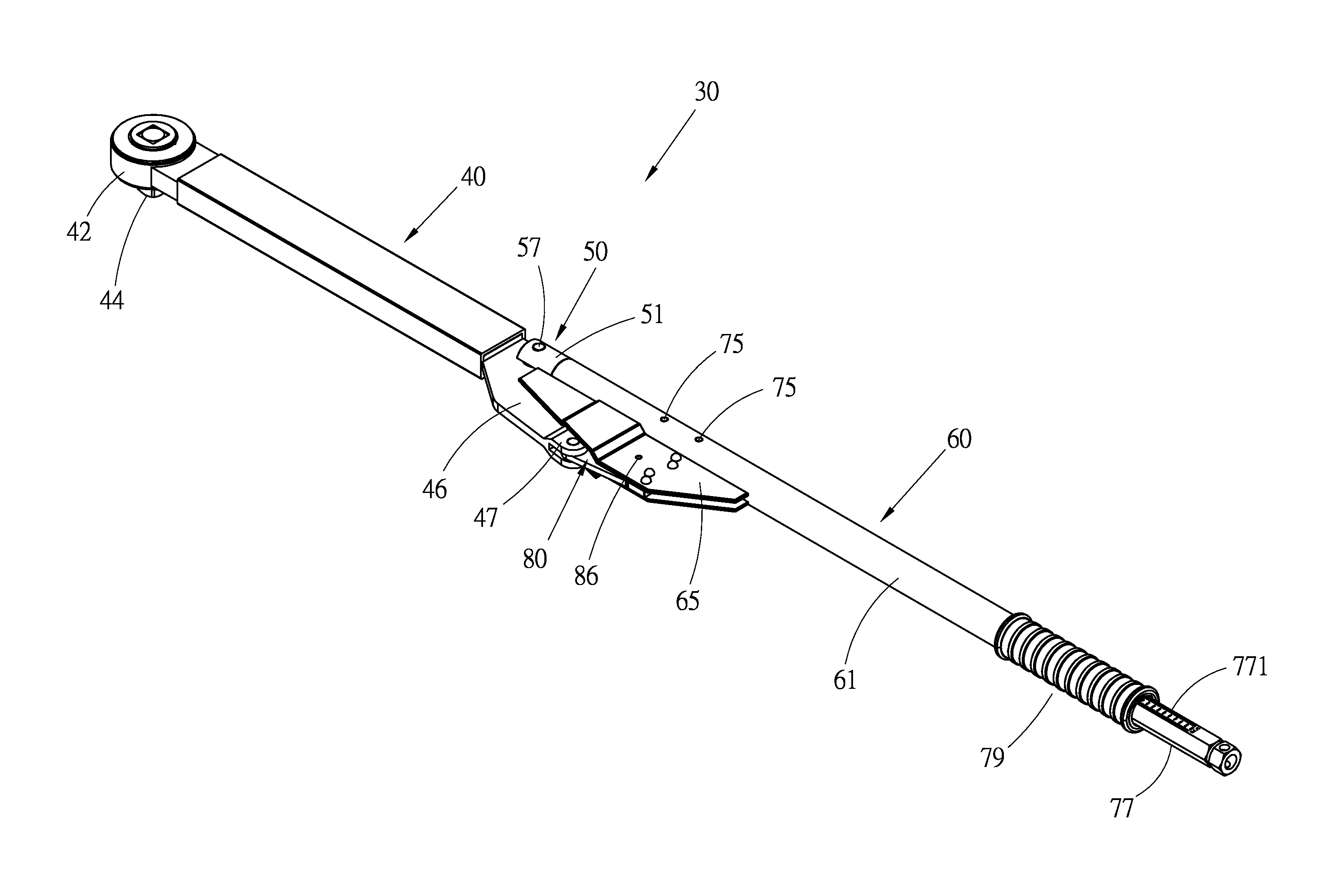
[0032]Please refer to FIGS. 4 to 6. According to a preferred embodiment, the collapsible torque wrench 30 of the present invention includes a shank 40. A drive head 42 is disposed at a front end of the shank 40. In this embodiment, the drive head 42 is a ratchet structure having a ratchet wheel 421. The ratchet wheel 421 is formed with a quadrangular fitting hole 422. An insertion pin 44 is inserted in the fitting hole 422 and elastically located therein. The insertion pin 44 is inserted in a socket (not shown) to connect the drive head 42 with the socket. The socket is fitted onto a threaded member to wrench the same. The form of the drive head 42 is not limited to the above embodiment. A first pivoted end 45 is disposed at a rear end of the shank 40. The shank 40 further has a branch bar 46 laterally extending from the rear end of the shank. A rear end of the branch bar 46 forms a second pivoted end 47 of the shank. The second pivoted end 47 has the form of two lugs. The first and...


PUM


Abstract

A collapsible torque wrench includes: a shank having a drive head at a front end and two pivoted ends at a rear end; a connection rod, a front end of which being pivotally connected with the first pivoted end; a housing having a tubular body and a casing fixedly disposed on one side of the tubular body, the connection rod being relatively slidably fitted in the tubular body; a torque adjustment mechanism being mounted in the tubular body and including a fixing block, the fixing block being mounted in the tubular body by at least two pins; and a stop member received in the casing. A front end of the stop member is pivotally connected with the second pivoted end. The fixing block is easily demounted from the tubular body for replacement.

Description

BACKGROUND OF THE INVENTION[0001]1. Field of the Invention[0002]The present invention relates generally to a torque wrench, and more particularly to a collapsible torque wrench.[0003]2. Description of the Related Art[0004]A conventional torque wrench generally has torque setting function. In the case that the wrenching torque applied by the wrench to a threaded member exceeds the set value, a warning effect is created to warn a user to stop wrenching.[0005]FIGS. 1 to 3 show a conventional torque wrench 10. The torque wrench 10 includes a shank 12. A drive head 14 is disposed at a front end of the shank 12 for connecting with a socket or fitting onto a threaded member. A rear end of the shank 12 is a pivoted end 13. A branch bar 15 is disposed on one side of the shank 12. The torque wrench 10 further includes a connection rod 16. A front end of the connection rod 16 is pivotally connected with the pivoted end 13 of the shank 12 via a pivot pin 161. The torque wrench 10 further includ...

Claims


Application Information

Patent Timeline
Patent Type & Authority Patents(United States)
IPC IPC(8): B25B23/142B25B13/46
CPCB25B23/1427B25B13/462
Inventor HSIEH, CHIH-CHING
Owner KABO TOOL COMPANY
Why Eureka
Try Eureka