Attachment having a module and an electronics atachment

a technology of electronics ata and module, which is applied in the direction of electrical apparatus, coupling device connection, support structure mounting, etc., can solve the problems of affecting the electrical and mechanical development of the connection means, the design of the connection system for the solution is very complex, and the change in production tasks, so as to prevent overheating of the connection module and the effect of being handled particularly easily

Active Publication Date: 2016-09-27
WEIDMULLER INTERFACE GMBH & CO KG
View PDF37 Cites 5 Cited by
  • Summary
  • Abstract
  • Description
  • Claims
  • Application Information

AI Technical Summary

Benefits of technology

[0030]In the assembled state, it is preferred that each time a connection module is arranged in a slot and is attached on the first mounting rail. In addition, the adapter is slipped onto the connection module and the printed circuit board arrangement. For this purpose, it preferably bears against the connection module. Likewise, the adapter is preferably arranged transverse to the printed circuit board and parallel to the electrical connection module. In this arrangement, the angle between the first and second connectors makes it difficult for the adapter to be intermittently disconnected by shaking. As a result, also the connectors cannot be dislodged from the mating adapters, so that the electrical contact is safely assured even when subjected to strong vibrations.
[0031]In the alternative embodiment, in which the printed circuit board arrangement includes

Problems solved by technology

On the one hand, strict security requirements exist for control signal transmission, posing major challenges for the electrical and mechanical development of the connection means.
On the other hand, changes in the production task frequently require resetting of the

Method used


Image

  • Attachment having a module and an electronics atachment
  • Attachment having a module and an electronics atachment
  • Attachment having a module and an electronics atachment

Examples


Embodiment Construction

FIGS. 1a-3

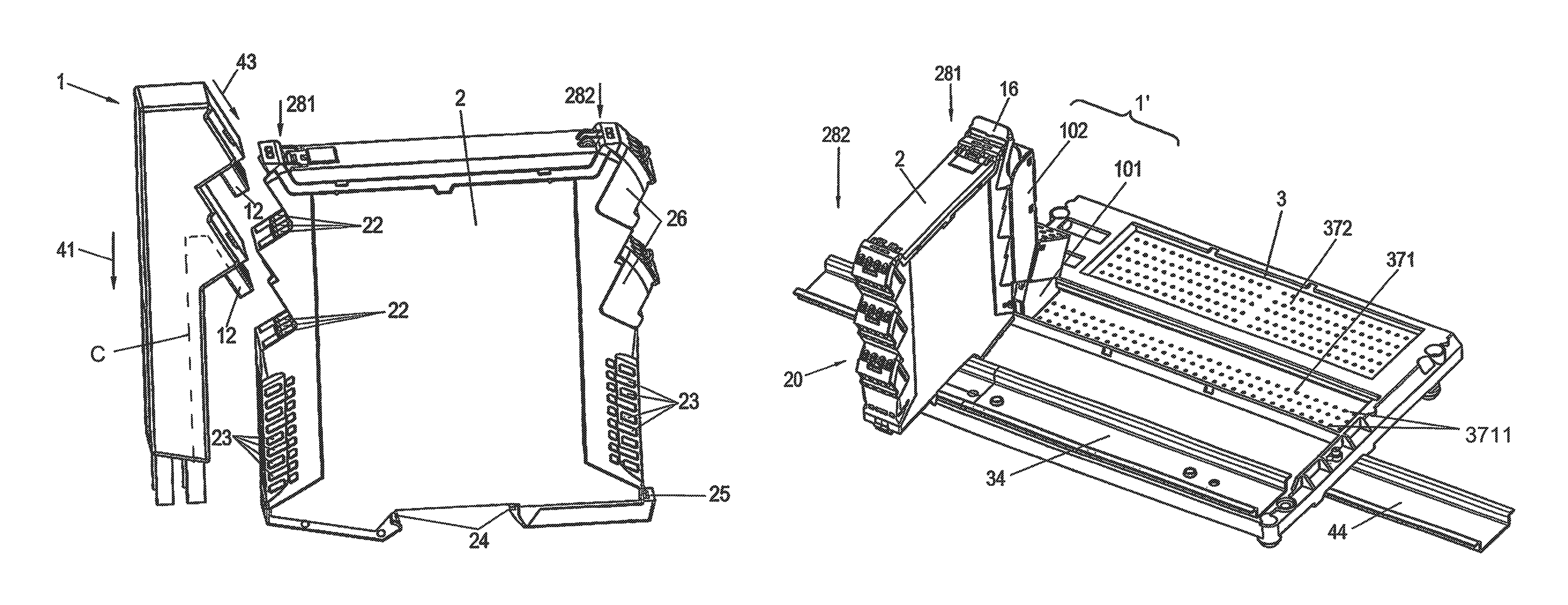
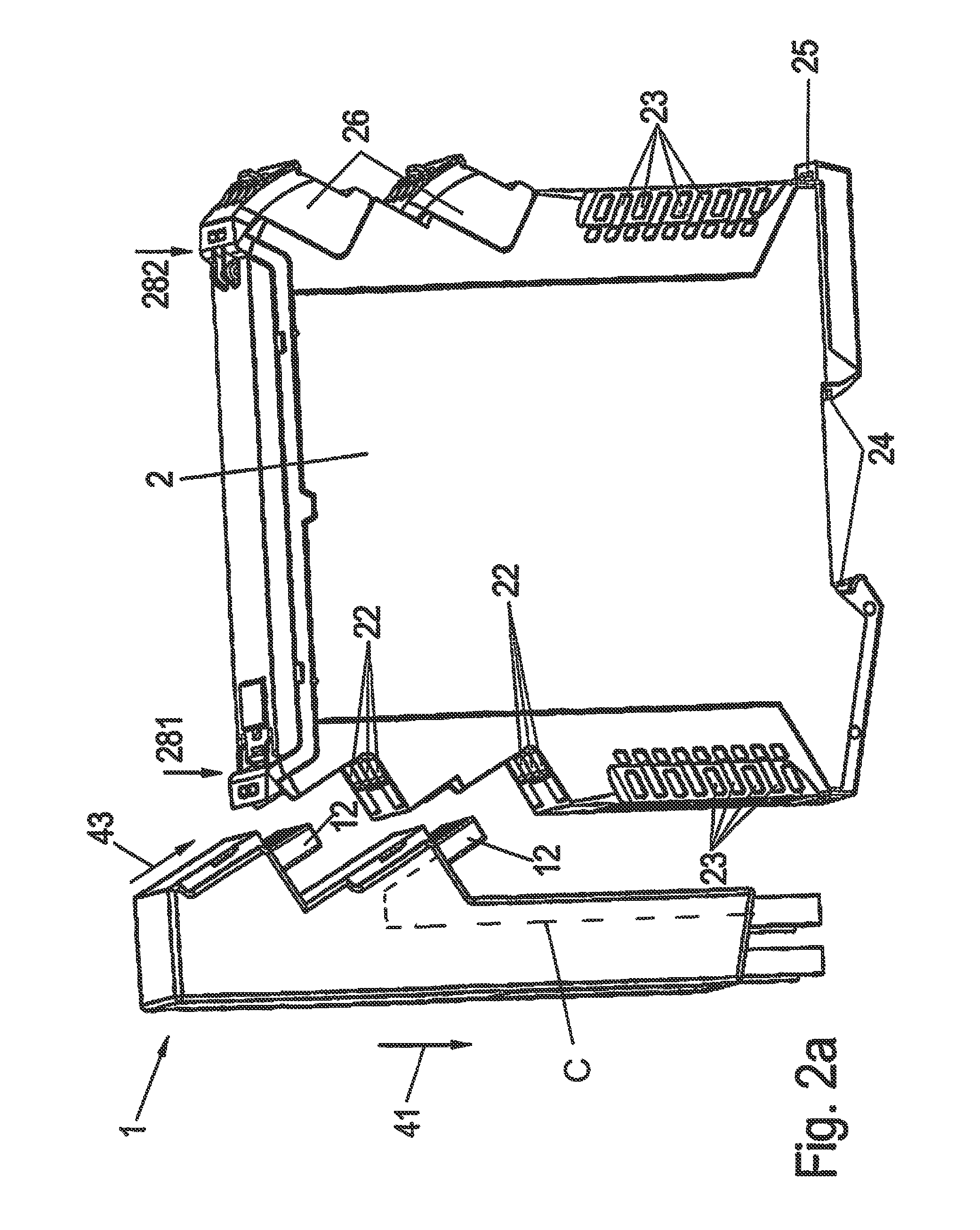
[0048]Referring first more particularly to FIG. 3, in accordance with the present invention, the adapter connector 1 is designed to electrically connect the terminals at one end 281 of an electronics module 2 with corresponding contacts 31 of a printed circuit board arrangement 3. At its other end 282, the module 2 is provided with connectors 26 having contacts 27 that are connected with various control systems (not shown). The bottom 29 of the module is connected with a module mounting rail 34 by releasable locking means 25. A plurality of modules are mounted in slots 33 defined on the PCB assembly 3 by partitions 32 having back walls 321. A main mounting rail 44 serves to mount the PCB assembly upon a fixed support (not shown). A bus bar 35 mounted in the module mounting rail 34 has tracks 351 for supplying electrical power and control signals to the contacts 31 of the PCB assembly 3, and then to the modules 2 via the adapter 1.

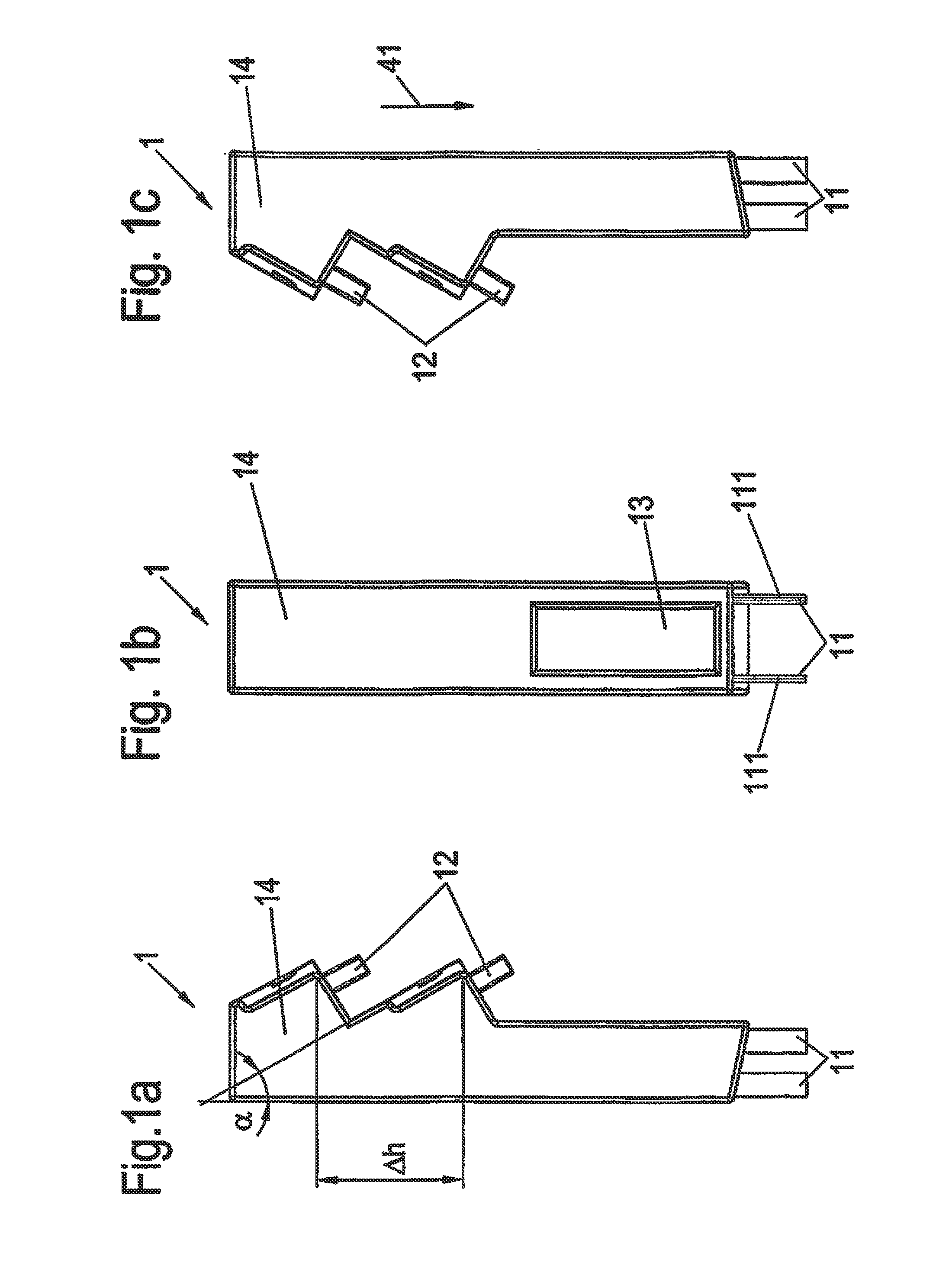
[0049]FIG. 1 shows an adapter 1 for connect...


PUM


Abstract

An adapter arrangement for electrically connecting an upwardly directed first contact on a horizontal printed circuit board assembly with a generally upwardly directed second contact on an electronics module mounted on the PCB assembly, including a rigid adapter housing adapted for mounting on one end of the module, which housing contains a generally vertical conductor having a lower end connected by a downwardly directed lower terminal with the PCB assembly first contact, and an upper end connected by a generally downwardly-directed upper terminal with the electronics module second contact, characterized in that the lower adapter terminal is vertical, and the upper adapter terminal is downwardly inclined by an acute angle relative to the vertical. In a second embodiment, the adapter is sectional and includes upper and lower sections. In a third embodiment, an auxiliary adapter section is connected between the upper adapter section and the electronics module.

Description

REFERENCE TO RELATED APPLICATIONS[0001]This application is a national stage application under 35 C.F.R. §371 of the PCT International Application No. PCT / EP2014 / 050432 filed Jan. 13, 2014, which claims priority of the German application No. DE 200 2013 100 208.9 filed Jan. 15, 2013.BACKGROUND OF THE INVENTION[0002]1. Field of the Invention[0003]An adapter arrangement for electrically connecting an upwardly-directed first contact on a horizontal printed circuit board assembly with a generally upwardly-directed second contact on an electronics module mounted on the PCB assembly, including a rigid housing adapted for mounting on one end of the module, which housing contains a generally vertical conductor having a lower end connected by a downwardly directed lower terminal with the PCB assembly first contact, and an upper end connected by a generally downwardly-directed upper terminal with the electronics module second contact, characterized in that the lower adapter terminal is vertica...

Claims


Application Information

Patent Timeline
IPC IPC(8): H01R25/14H01R13/633H05K7/14H01R12/70H01R25/16
CPCH01R12/7076H01R13/633H01R25/162H05K7/1469
Inventor BUSCH, GERALDSALTAJL, SAFWANDREIFERT, SASCHA
Owner WEIDMULLER INTERFACE GMBH & CO KG
Why Eureka
Try Eureka