Supercharge Your Innovation With Domain-Expert AI Agents!

Systems, methods, and apparatus for modifying sensor time stamp data

a technology of sensor time stamp and time stamp data, applied in the field of sensor data, can solve the problems of inability to accurately represent the monitored phenomena, many reliability problems, space challenges, interference, etc., and achieve the effect of reducing the cost of monitoring and monitoring, and increasing the cost of monitoring

Inactive Publication Date: 2016-09-27
GENERAL ELECTRIC CO
View PDF6 Cites 3 Cited by
  • Summary
  • Abstract
  • Description
  • Claims
  • Application Information

AI Technical Summary

Benefits of technology

The patent text describes a system, method, and apparatus for modifying sensor time stamp data. This involves receiving packet or datagram data from sensors or IEDs, examining time stamps associated with the data, and determining a variance between the time stamps or an offset between the time stamps and an accurate time source. The technical effect of the invention is to improve the accuracy and reliability of timing data captured from sensors or IEDs.

Problems solved by technology

In many applications, multiple sensors can be utilized in conjunction with a system, but connecting all of the sensors with their associated communication wires to a central panel can present many reliability issues, space challenges, interference, and other issues.
However, when the local clocks or time sources that provide the time stamps are not synchronized to a global time source, the received data, when re-assembled according to time stamps, can present an inaccurate representation of the monitored phenomena.
Synchronizing local time sources to reduce time stamp error associated with each sensor or IED may be possible, but it can be prohibitively expensive.
For example, a broadcast global positioning system (GPS) signal may be received by sensors or IEDs for synchronization of each component's associated time source, but the GPS receivers may cost more than the sensors, or there may be line-of-sight restrictions that prohibit reception of the synchronization signals.
High quality crystals may be utilized with local time sources, but drift over time can still be an issue that can cause loss of time-synchronization.

Method used


Image

  • Systems, methods, and apparatus for modifying sensor time stamp data
  • Systems, methods, and apparatus for modifying sensor time stamp data
  • Systems, methods, and apparatus for modifying sensor time stamp data

Examples


Embodiment Construction

[0014]Embodiments of the invention will be described more fully hereinafter with reference to the accompanying drawings, in which embodiments of the invention are shown. This invention may, however, be embodied in many different forms and should not be construed as limited to the embodiments set forth herein; rather, these embodiments are provided so that this disclosure will be thorough and complete, and will fully convey the scope of the invention to those skilled in the art. Like numbers refer to like elements throughout.

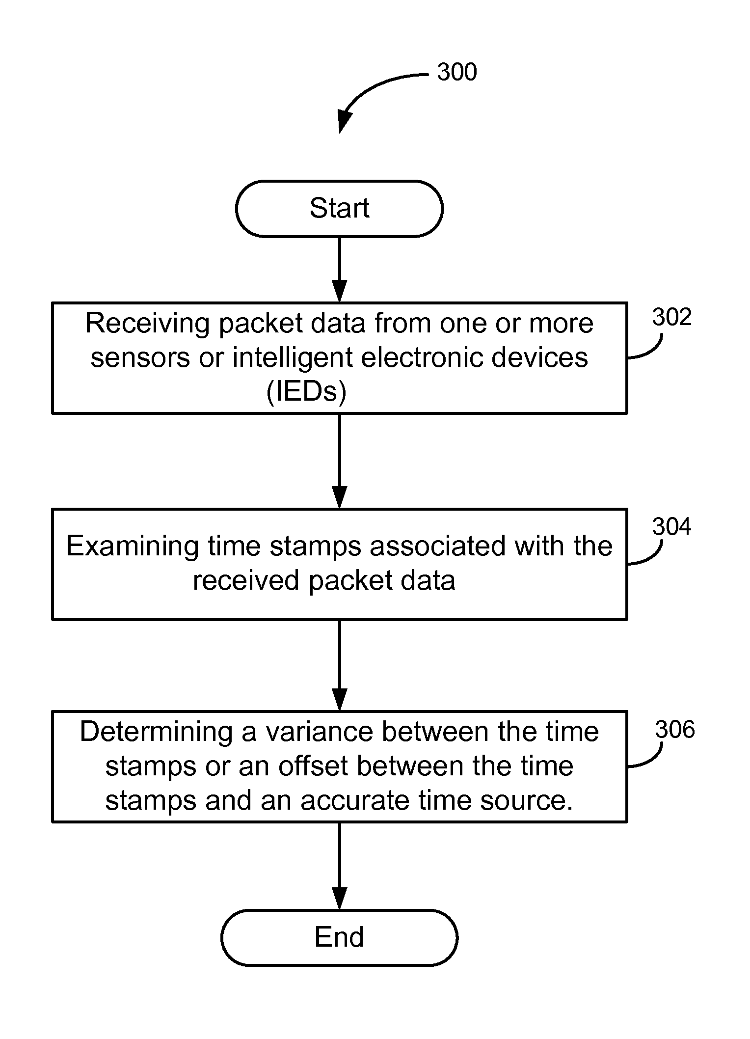
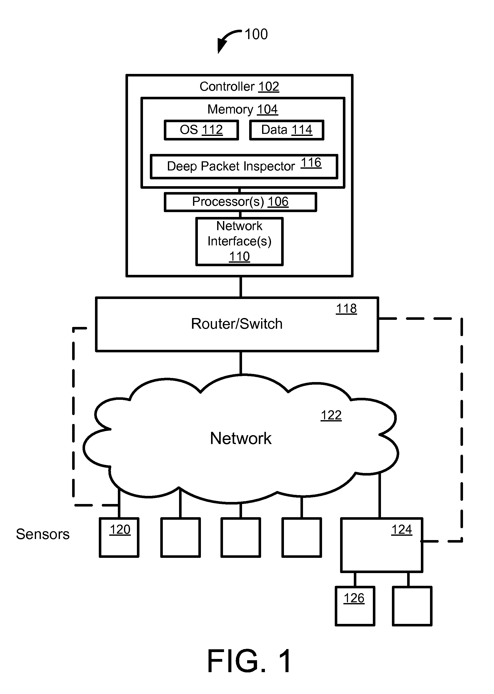
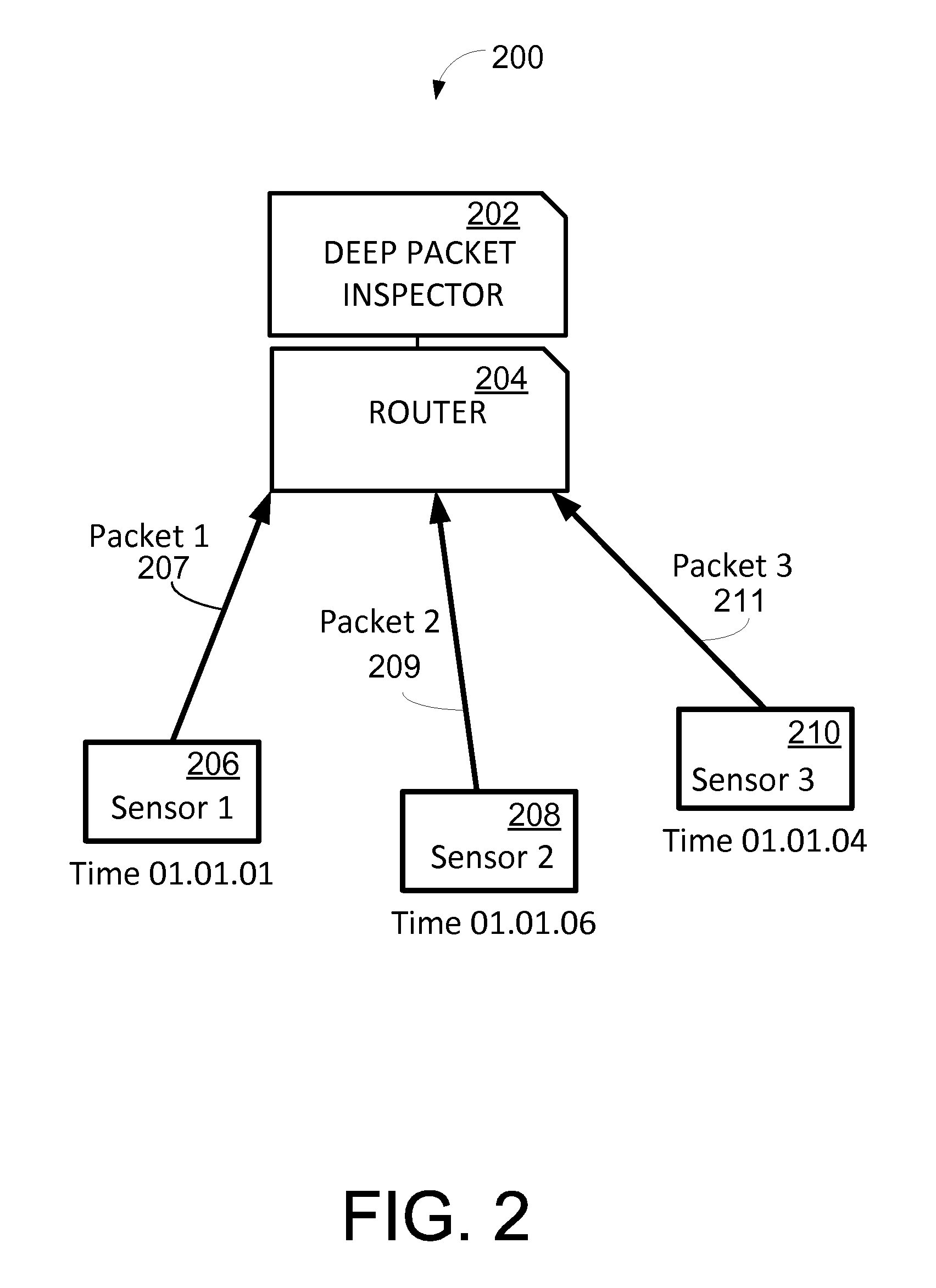
[0015]Certain embodiments of the invention may enable monitoring and revising time stamps associated with sensor data. According to certain example embodiments, a deep packet inspection may be performed at an aggregation point. According to example embodiments, the time stamps may be revised or re-stamped using a global or reference time source. For example, time derived from global positioning system (GPS) signals, or from a network may be utilized for revising ...


PUM


Abstract

Certain embodiments of the invention may include systems, methods, and apparatus for modifying sensor time stamp data. According to an example embodiment of the invention, a method is provided for monitoring and correcting sample time stamps. The method can include receiving packet data from one or more sensors or intelligent electronic devices (IEDs); examining time stamps associated with the received packet data; and determining a variance between the time stamps or an offset between the time stamps and an accurate time source.

Description

FIELD OF THE INVENTION[0001]This invention generally relates to sensor data, and in particular to modifying sensor time stamp data.BACKGROUND OF THE INVENTION[0002]Sensors are utilized in numerous industrial applications for measuring and monitoring phenomena. In many applications, multiple sensors can be utilized in conjunction with a system, but connecting all of the sensors with their associated communication wires to a central panel can present many reliability issues, space challenges, interference, and other issues. To address some of these challenges and issues, sensors and intelligent electronic devices (IEDs) have been developed that can communicate over serial bus, Ethernet, etc., where the measured data can be digitized, time-stamped, formatted for communication, and sent through the data channel or network, eliminating many unnecessary cables.[0003]In many cases, time stamps are applied to the data by the local sensors or IEDs. However, when the local clocks or time sour...

Claims


Application Information

Patent Timeline
Patent Type & Authority Patents(United States)
IPC IPC(8): H04L12/26
CPCH04L43/028H04L43/10H04L43/16Y04S40/168H02H1/0061H02H3/28H02H3/30H02H7/263Y04S40/00
Inventor BOOT, JOHN CHRISTOPHER
Owner GENERAL ELECTRIC CO
Features
  • R&D
  • Intellectual Property
  • Life Sciences
  • Materials
  • Tech Scout
  • Unparalleled Data Quality
  • Higher Quality Content
  • 60% Fewer Hallucinations
Learn More