Eureka AIR delivers breakthrough ideas for toughest innovation challenges, trusted by R&D personnel around the world.

Methods and apparatus for bandwidth management in a telecommunications system

Active Publication Date: 2016-09-27
RIBBON COMM OPERATING CO INC
View PDF8 Cites 20 Cited by
  • Summary
  • Abstract
  • Description
  • Claims
  • Application Information

AI Technical Summary

Benefits of technology

The present invention addresses the problem of congestion on a link caused by a large number of packets being dropped in a bursty manner for rate control functions. By reserving bandwidth for new packet flows and applying rate control functions to opportunistic rate traffic flows in a gradual and graceful manner, the invention reduces the risk of shocks to the opportunistic rate traffic flows and avoids congestion on the link. This improves the chances of allowing a new real time packet flow to proceed without delay and increases the likelihood of having capacity on the link being shared for a new real time traffic flow.

Problems solved by technology

Because of the varied bandwidth requirements of real time traffic, opportunistic rate traffic, and control and signaling traffic, it is quite challenging and difficult to reserve and allocate the proper amount of bandwidth to satisfy the needs of the various incoming data packet streams' bandwidth requests.
This makes it quite difficult to reserve resources and to decide whether a new MSRP session request should be accepted or rejected.
This variation can potentially affect the committed bandwidth for RTP media sessions, which in turn affects the quality of voice and video payload carried within RTP flows.
Moreover, attempting to optimize the use of a link's bandwidth through bandwidth sharing can lead to additional problems and difficulties in how to control, police, and / or enforce bandwidth allocation and usage policies.

Method used


Image

  • Methods and apparatus for bandwidth management in a telecommunications system
  • Methods and apparatus for bandwidth management in a telecommunications system
  • Methods and apparatus for bandwidth management in a telecommunications system

Examples


Embodiment Construction

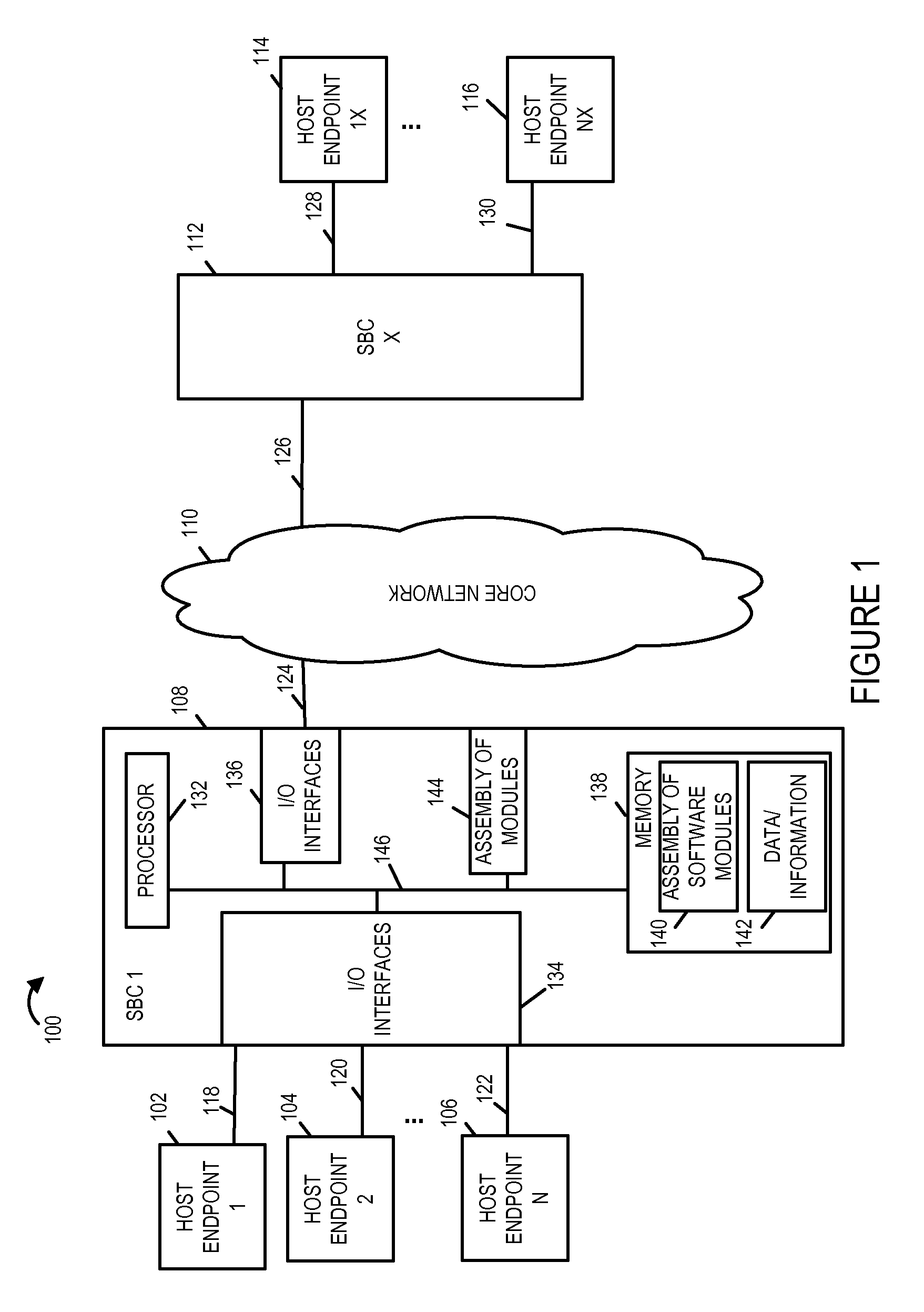
[0038]FIG. 1 illustrates an exemplary system 100 implemented in accordance with an exemplary embodiment of the invention. System 100 includes a plurality of host devices also referred to as end points (host end point 1 102, host end point 2 104, . . . , host end point N 106) which are coupled to a session border controller 1 (SBC 1) 108 through links (118, 120, . . . , 122) respectively. SBC 1 108 is coupled to a core network 110 via link 124. Additional links may also be used to connected SBC 1 108 to the core network 110. System 100 further includes a second session border controller, SBC X 112, which is coupled to the core network 110 via link 126. Additional links may also be used to connect SBC X 112 and the core network 110. SBC X 112 is also coupled to a plurality of host device end points (host endpoint 1X 114, . . . , host endpoint NX 116) via links (128, . . . , 130), respectively. The core network 110 may include one or more network elements. The session border controller...


PUM


Abstract

Methods and apparatus for sharing bandwidth over a link in a packet-oriented telecommunications system or network that supports multiple types of traffic including, e.g., real time packet flows, opportunistic rate packet flows, control and signaling traffic, are described. In one exemplary embodiment the method includes the steps of receiving a bandwidth allocation request requesting allocation of a required amount of bandwidth for a new real time packet flow, allocating the requested bandwidth from bandwidth reserved for newly-allocated real time packet flows, updating the measure of the total amount of bandwidth allocated to real time packet flows to reflect the allocation of the bandwidth to the new real time packet flow, and generating new bandwidth allocations for existing opportunistic rate packet flows based on a measure of the total amount of bandwidth allocated to real time packet flows. Some embodiments of the invention include methods to enforce the dynamic bandwidth allocations.

Description

RELATED APPLICATIONS[0001]The present application claims the benefit of U.S. Provisional Patent Application Ser. No. 61 / 718,640 filed Oct. 25, 2012, entitled “METHODS AND APPARATUS FOR BANDWIDTH MANAGEMENT IN A TELECOMMUNICATIONS SYSTEM”, which is hereby expressly incorporated by reference in its entirety.FIELD OF INVENTION[0002]The present invention relates to methods and apparatus for bandwidth management in packet-oriented telecommunications systems and / or networks.BACKGROUND OF THE INVENTION[0003]The fixed and limited amount of bandwidth, i.e. capacity, on a telecommunications or network link make it generally necessary to have a bandwidth allocation and enforcement strategy to maximize the use of this limited resource. In packet-oriented telecommunications systems or networks, the data traffic to be transmitted on a link is packetized and transmitted as data packet flows. The data traffic is typically classified so that in those instances where there is insufficient bandwidth o...

Claims


Application Information

Patent Timeline
IPC IPC(8): H04L12/873H04L12/911H04L12/853H04L29/06H04L12/801H04L47/52H04L47/2416
CPCH04L47/522H04L47/70H04L47/2416H04L69/14H04L47/10
Inventor NAYAK, SUBHRANSU SDUFFY, MARKASVEREN, TOLGALI, SHIPINGPILOTTE, KEVIN
Owner RIBBON COMM OPERATING CO INC
Why Eureka
Eureka Blog
Learn More