Liquid ejection device and dummy jet method

a liquid ejection device and jet technology, applied in printing, inking apparatus, other printing apparatus, etc., can solve the problems of mist generation, crosstalk and instability, affecting the movement of mist, etc., and achieve the reduction of the amount of mist moving to the liquid ejection surface, the effect of reducing the probability of mist moving to, and reducing the amount of ascending air current generated

Active Publication Date: 2016-10-04
FUJIFILM CORP
View PDF13 Cites 0 Cited by
  • Summary
  • Abstract
  • Description
  • Claims
  • Application Information

AI Technical Summary

Benefits of technology

[0024]According to the invention, the plurality of nozzle portions which are supplied with the liquid from the same supply flow path are divided into two or more groups. For the period for which the dummy jet is performed for one group, the non-ejection driving voltage for preventing the liquid from being ejected is supplied to the other groups. Therefore, the nozzle portions which eject the liquid are distributed. A region in which a descending air current from the liquid ejection surface is generated is widened and a region in which an ascending air current to the liquid ejection surface is generated is narrowed. The probability of mist moving to the region in which the ascending air current is generated is reduced. As a result, the amount of mist moving to the liquid ejection surface is reduced and the attachment of mist to the liquid ejection surface is suppressed.

Problems solved by technology

Therefore, the ejection is affected by crosstalk and is unstable.
As a result, there is a concern that mist will be generated.
Therefore, there is a concern that mist will be generated due to crosstalk which is caused by the ejection of ink from adjacent nozzles in a short cycle.

Method used


Image

  • Liquid ejection device and dummy jet method
  • Liquid ejection device and dummy jet method
  • Liquid ejection device and dummy jet method

Examples


Embodiment Construction

[0059]Hereinafter, preferred embodiments of the invention will be described with reference to the accompanying drawings.

[0060][Overall Structure of Ink Jet Recording Device]

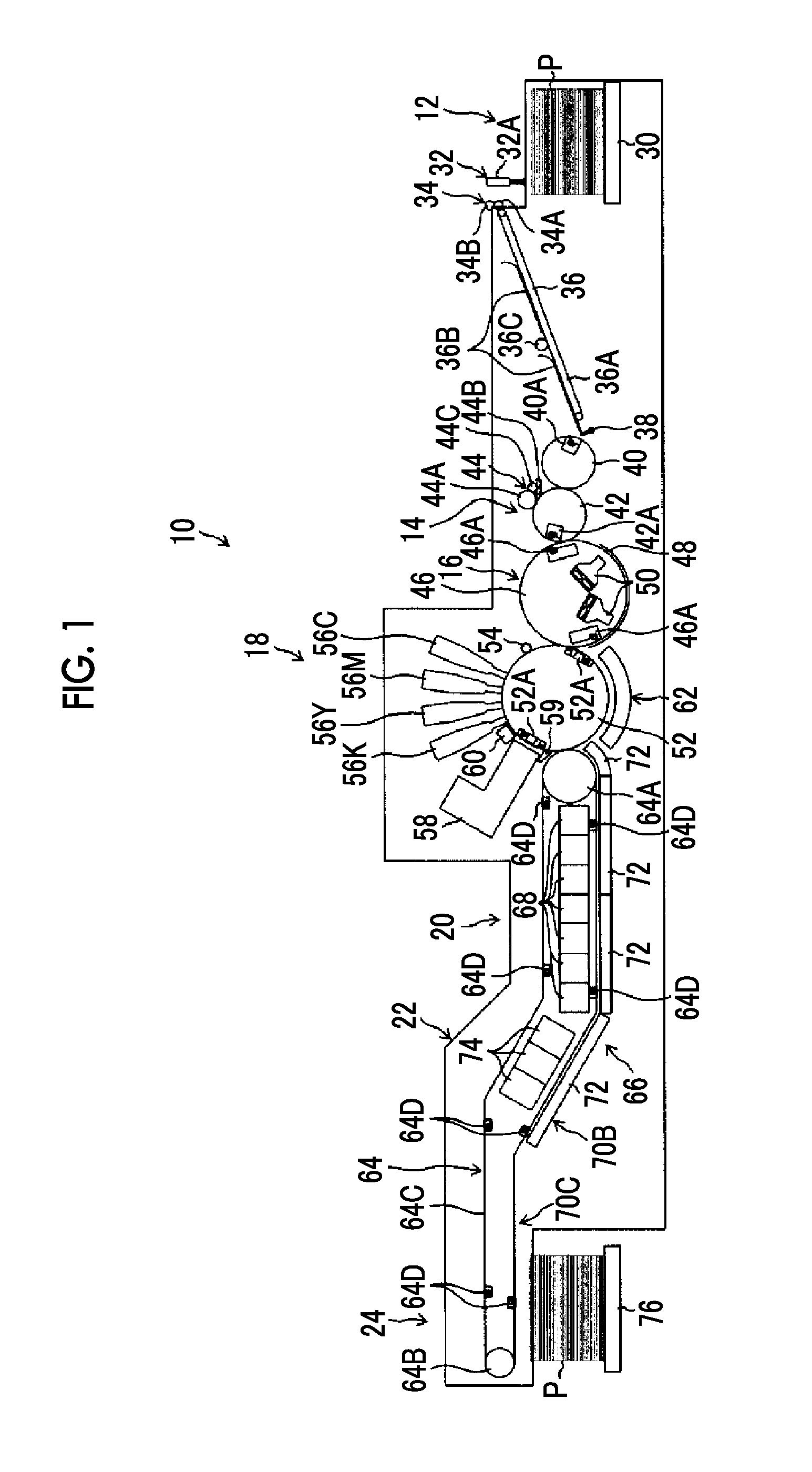
[0061]FIG. 1 is a diagram illustrating the overall structure of an ink jet recording device (liquid ejection device) to which an ink jet head (liquid ejection head) according to an embodiment of the invention is applied.

[0062]An ink jet recording device 10 illustrated in FIG. 1 is an ink jet recording device which records an image on a sheet P in an ink jet manner using an aqueous ultraviolet (UV) ink (UV curable ink using an aqueous solvent).

[0063]The ink jet recording device 10 includes a sheet feed unit 12, a process liquid applying unit 14, a process liquid drying processing unit 16, an image forming unit 18, an ink drying processing unit 20, a UV irradiation processing unit 22, and a sheet discharge unit 24. The sheet feed unit 12 feeds the sheet P. The process liquid applying unit 14 applies a process liqui...


PUM


Abstract

A liquid ejection device includes an ink jet head in which a plurality of nozzle portions are arranged in a matrix; a plurality of pressurizing elements that generate an ejection force; and a driving voltage supply unit that supplies a driving voltage to the pressurizing elements. In the device, the ink jet head is provided with supply flow paths, the nozzle portions which are supplied with the liquid from the same the supply flow path are divided into two or more groups, the driving voltage supply unit supplies an ejection driving voltage for ejecting the liquid to each of the groups when a dummy jet is performed, and during a period of time when the dummy jet is performed for one group, the driving voltage supply unit supplies a non-ejection driving voltage for preventing the liquid from being ejected to the other groups.

Description

CROSS-REFERENCE TO RELATED APPLICATIONS[0001]This application is a Continuation of PCT International Application No. PCT / JP2014 / 058123 filed on Mar. 24, 2014, which claims priority under 35 U.S.C §119(a) to Japanese Patent Application No. 2013-073414 filed on Mar. 29, 2013, and Japanese Patent Application No. 2013-137026 filed on Jun. 28, 2013. Each of the above applications is hereby expressly incorporated by reference, in its entirety, into the present application.BACKGROUND OF THE INVENTION[0002]1. Field of the Invention[0003]The present invention relates to a liquid ejection device and a dummy jet method, and more particularly, to a dummy jet for an ink jet head.[0004]2. Description of the Related Art[0005]In some types of ink jet head which use ink (for example, an aqueous pigment ink) using an aqueous solvent, a nozzle portion dries in the following situation and an ejection performance deteriorates.[0006]When the nozzle portion is left unused in a standby cap portion, it is d...

Claims


Application Information

Patent Timeline
Patent Type & Authority Patents(United States)
IPC IPC(8): B41J29/38B41J2/14B41J2/17B41J2/045B41J2/165
CPCB41J2/0453B41J2/14233B41J2/16508B41J2/16526B41J2/16585B41J2/1714B41J2002/14459B41J2002/1657B41J2202/12B41J2202/20B41J2202/21
Inventor KATSUMURA, MANABUMITA, TSUYOSHI
Owner FUJIFILM CORP
Why Eureka
Try Eureka