Apparatus for cooling media sheets

a technology of cooling media and cooling media, which is applied in the direction of printing, printing, electromagnetography, etc., can solve the problems of adding to the total energy consumption of the printer, and achieve the effect of reducing energy consumption

Active Publication Date: 2016-10-04
OCE TECH
View PDF13 Cites 3 Cited by
  • Summary
  • Abstract
  • Description
  • Claims
  • Application Information

AI Technical Summary

Benefits of technology

[0010]It is an object of the present invention to provide a cooling apparatus, which permits to appropriately cool the sheets with reduced energy consumption, at least under certain operating conditions of the printer.
[0012]This arrangement permits energy savings when the admissible residual temperature of the sheets depends upon the destination to which the sheets are to be directed. For example, the print process may be such that, in order to obtain a high print quality, the temperature of the sheets at entry into the printing station must not exceed a certain limit. Consequently, in a duplex printer the sheets that have been printed already on one side and have therefore been heated in the print process must be cooled down sufficiently before they are re-circulated for printing on the second side, whereas duplex sheets that have been printed on both sides already or simplex sheets that are to be printed only on one side, anyway, are allowed to have a higher temperature when they are directed to the discharge tray. According to an embodiment of the present invention, the sheets for which a higher exit temperature is admissible will bypass the last cooling unit, whereby the energy consumption of this cooling unit is reduced.
[0013]The energy consumption of the last cooling unit may be reduced simply by the fact that only a smaller number of sheets is passed through this unit so that the amount of heat to be removed by this unit is smaller and, consequently, the required amount of cooling air is reduced or the admissible temperature of the cooling air may be higher so that less energy is needed in a refrigerating system for cooling the air.
[0014]The media sheets that have left the first cooling unit are decelerated in the first conveyor path, so that more time is available for cooling the sheets to a lower temperature in the last cooling unit. Consequently, the required low temperature for the sheets to be re-circulated can be reached with reduced total heat absorbing capacity of the cooling units, which permits not only to save energy, but also to reduce the space requirement for the cooling units.

Problems solved by technology

In any case, the necessary measures for cooling the sheets add to the total energy consumption of the printer.

Method used


Image

  • Apparatus for cooling media sheets
  • Apparatus for cooling media sheets

Examples


Embodiment Construction

[0022]The present invention will now be described with reference to the accompanying drawings, wherein the same reference numerals have been used to identify the same or similar elements throughout the several views.

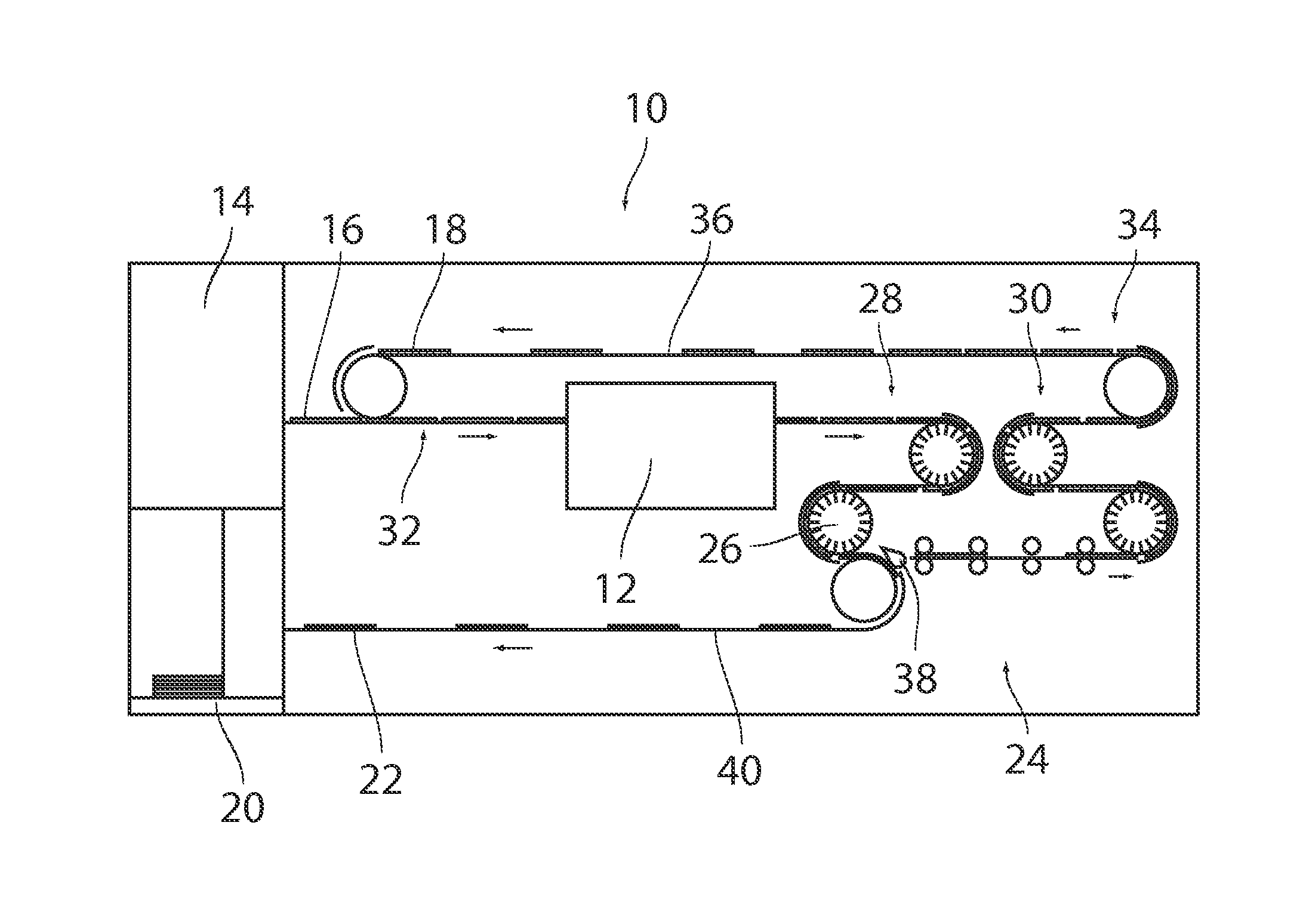
[0023]As has been shown schematically in FIG. 1, a printer 10 comprises a printing unit 12, a feeder 14 for feeding media sheets 16, 18 to the printing unit 12, and a discharge tray 20 onto which printed media sheets 22 are discharged.

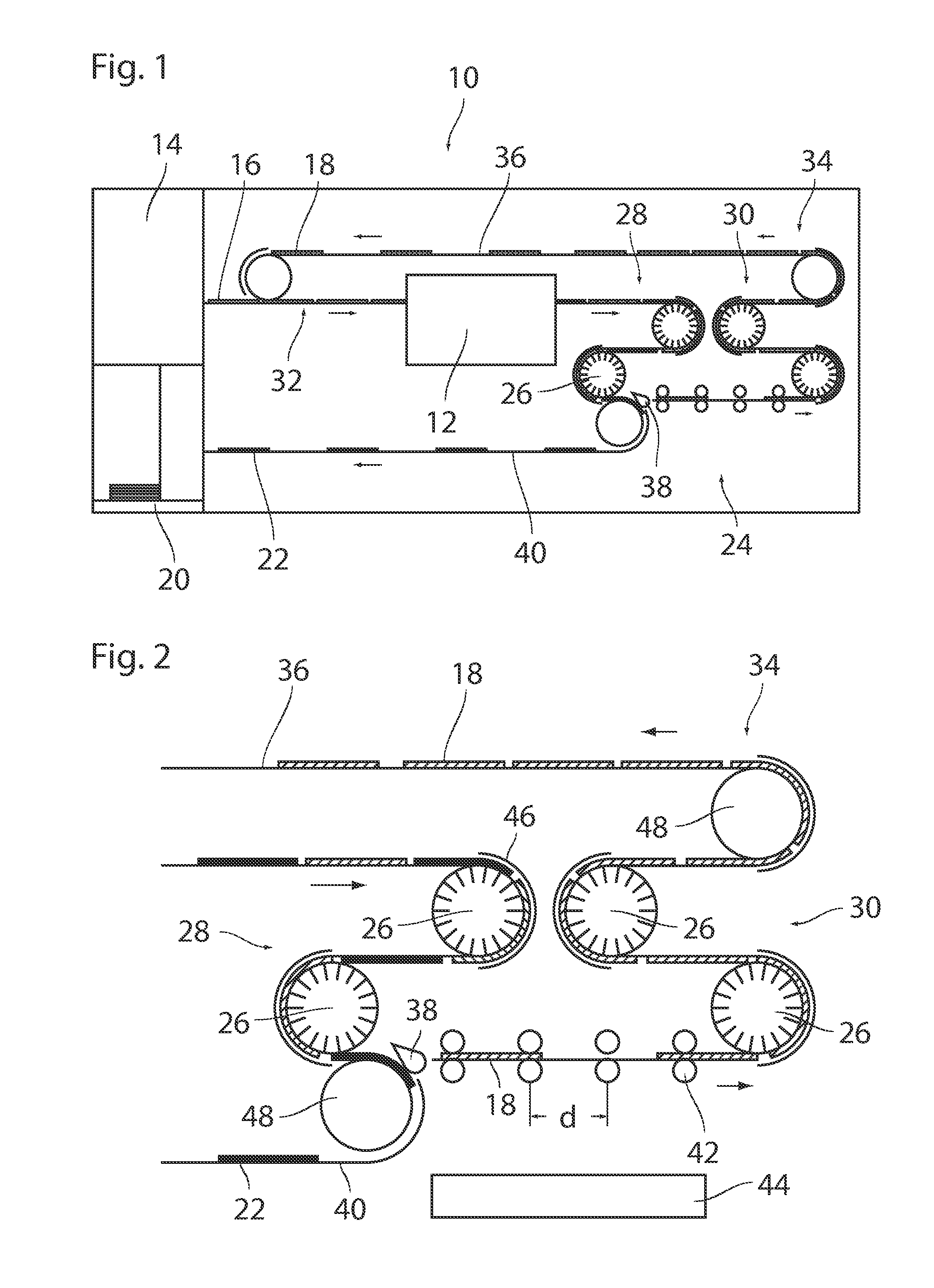
[0024]It shall be assumed here that the printing unit 12 employs a print process, e.g. laser printing or ink jet printing, in which the media sheets are heated to an elevated temperature, so that it is necessary to cool the sheets before they are discharged onto the discharge tray 20. For this reason, a sheet cooling apparatus 24 is provided on the exit side of the printing unit 12. The cooling apparatus 24 comprises a total of four cooling drums 26, two of the cooling drums 26 constitute a first cooling unit 28, while the other two cooling...


PUM


Abstract

An apparatus for cooling media sheets in a printer includes a number of cooling units, a conveyor having a first conveyor path adapted to feed the media sheets successively through the cooling units, and a switch adapted to deflect selected ones of the media sheets into a second conveyor path. The switch is disposed upstream of a last one of the cooling units and downstream of a first one of the cooling units. The second conveyor path bypasses the last one of the cooling units. The conveyor includes a decelerating mechanism configured to decelerate the sheets in the first conveyor path between the first one of the cooling units and the last one of the cooling units.

Description

CROSS-REFERENCE TO RELATED APPLICATIONS[0001]This application claims priority under 35 U.S.C. §119(a) to Application No. 14193048.7 filed in Europe on Nov. 13, 2014, the entire contents of which is hereby incorporated by reference into the present application.BACKGROUND OF THE PRESENT INVENTION[0002]1. Field of the Invention[0003]The present invention relates to an apparatus for cooling media sheets in a printer, the apparatus comprising: a number of cooling units; a conveyor having a first conveyor path adapted to feed the media sheets successively through the number of cooling units; and a switch adapted to deflect selected ones of the media sheets into a second conveyor path, wherein the switch is disposed upstream of a last one of the number of cooling units and downstream of a first one of the number of cooling units, and the second conveyor path bypasses the last one of the number of cooling units.[0004]2. Description of Background Art[0005]In a printer such as a laser printer...

Claims


Application Information

Patent Timeline
Patent Type & Authority Patents(United States)
IPC IPC(8): B41J29/377B41J13/00B41J3/60G03G15/23
CPCB41J29/377B41J3/60B41J13/009G03G15/235G03G21/20G03G21/203
Inventor AERTS, WILHELMUS J.LA VOS, PETER G.
Owner OCE TECH
Why Eureka
Try Eureka