Plug-in coupling and method for the production thereof

a plug-in coupling and plug-in technology, applied in the direction of sheet joining, fastening means, snap-action fasteners, etc., can solve the problem that both functions are not optimally implemented in the plug-in coupling

Active Publication Date: 2016-10-04
BOLLHOFF VERBINDUNGSTECHNIK GMBH
View PDF35 Cites 10 Cited by
  • Summary
  • Abstract
  • Description
  • Claims
  • Application Information

AI Technical Summary

Benefits of technology

[0009]The construction of the negative coupling part of the plug-in coupling may be based on the use of two materials of different elasticity for producing the negative coupling part. A material of lower elasticity and higher stability is used for producing the coupling construction in that the positive coupling part, for example a pin having a ball head, is accommodated and fastened. The low elasticity compared to the second material, and the high stability of the first material ensure that the pin having a ball head, thus the positive coupling part, is held reliably in the coupling construction. In order to be able to dampen possible vibrations between the first and the second component, and thus between the negative and the positive coupling part, the coupling construction is fastened to the second component via a retaining construction made of a second material. The material of the retaining construction has a higher elasticity, in comparison to the first material of the coupling construction, so that component vibrations from the first and second component can be damped and / or noises can be decoupled between components. The second material is thus more elastically deformable than the first material so that despite a reliably implemented fastening of the negative coupling part in the second component, a certain flexibility of the negative coupling part relative to the second component is guaranteed. This flexibility ensures along with a decoupling of vibrations also a tolerance compensation with the fastening of the first component to the second component via the plug-in coupling according to the invention. Because the coupling construction can be moved within a certain tolerance range in the lateral and axial direction via the elasticity of the second material of the retaining construction, misalignments between the first and second component or between the negative coupling part and the positive coupling part, can be compensated so that despite these misalignments an optimal connection can be implemented between the first and second component via the tolerance compensation of the negative coupling part.
[0012]According to a further embodiment of the present invention, the retaining construction of the negative coupling part is formed by a ring that is fastened to and surrounding the coupling construction, and that can be fastened in an opening of the second component. This ring may comprise a circumferential radial recess opening outward in the radial direction into which an inside of the opening of the second component can be received. According to a further embodiment, the ring, or respectively the retaining construction, comprises an axial recess open in the axial direction of the retaining construction and circumferential about the retaining construction, such that deformations of the retaining construction can be accommodated in the radial direction.

Problems solved by technology

The known plug-in couplings have the disadvantage that due to the material selection of the plug-in coupling, and due to the construction thereof, a compromise must be made in order to implement an optimal fastening of the ball pin within the negative coupling part and of the coupling part to a component, and a satisfactory damping of vibrations between the negative and positive coupling part.
This compromise has frequently led to the consequence that both functions are not optimally implemented in the plug-in coupling.

Method used


Image

  • Plug-in coupling and method for the production thereof
  • Plug-in coupling and method for the production thereof
  • Plug-in coupling and method for the production thereof

Examples


Embodiment Construction

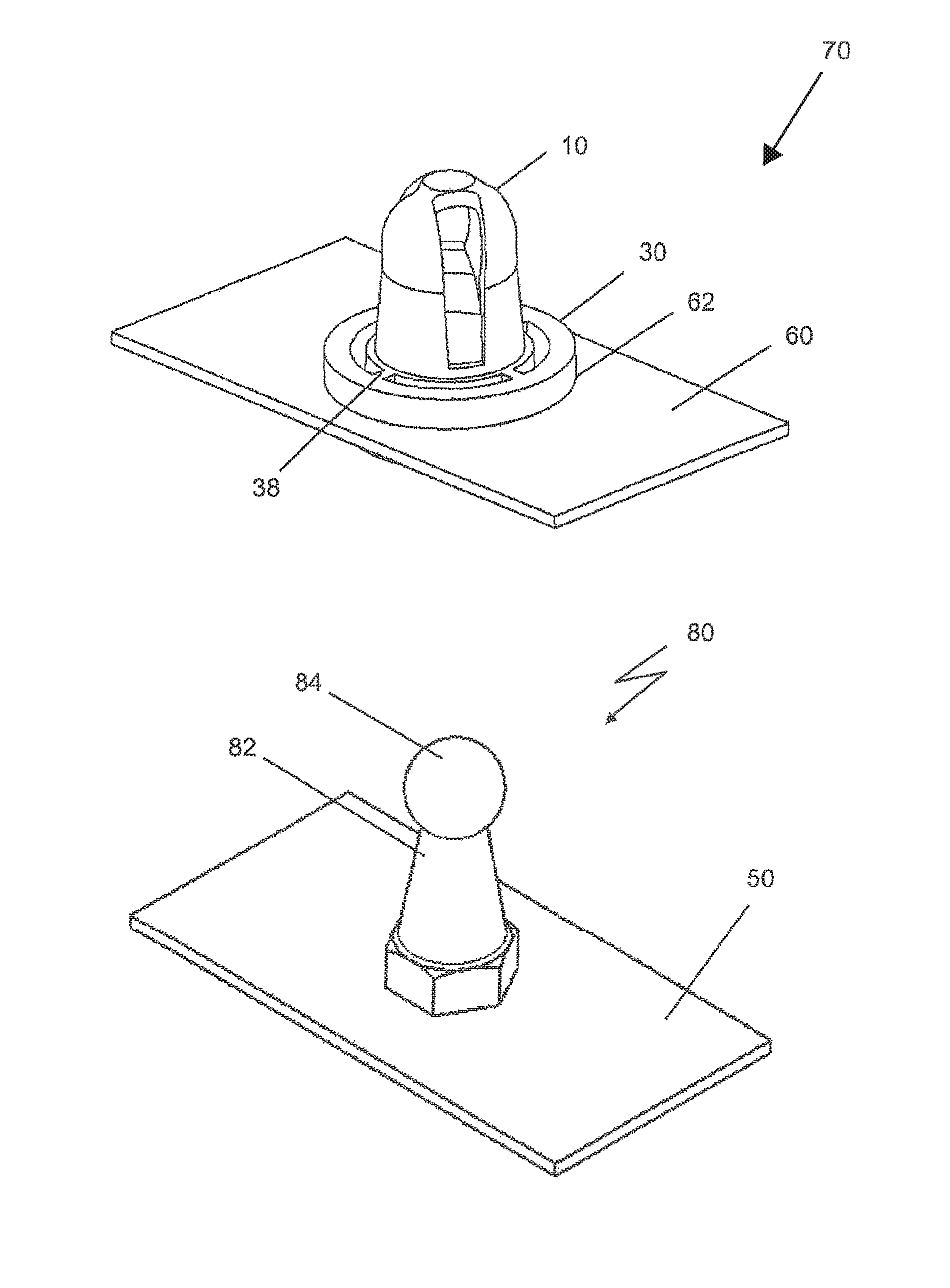
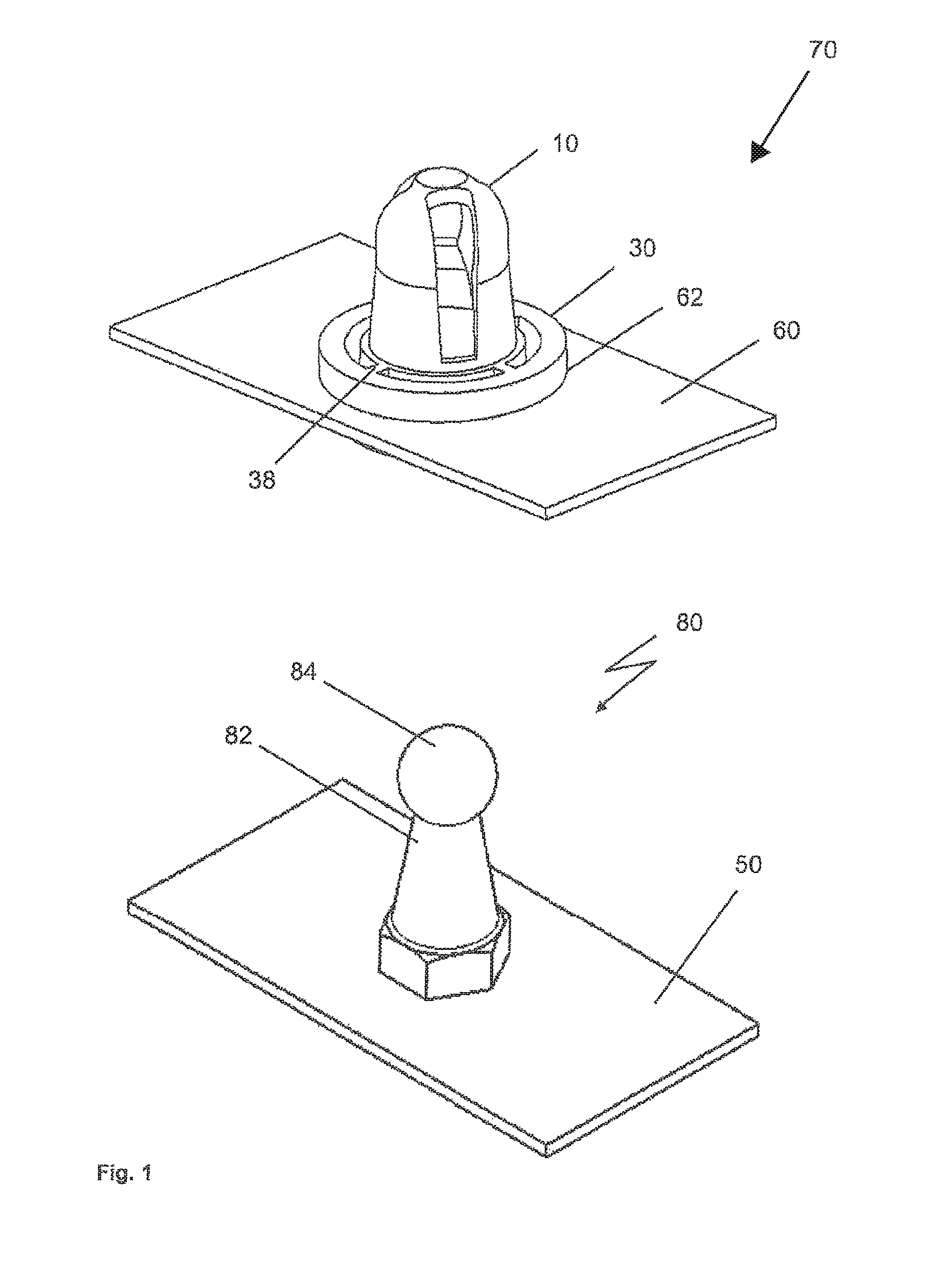
[0027]FIG. 1 shows a presently preferred embodiment of the plug-in coupling 70. The plug-in coupling 70 consists of a positive coupling part 80 that can be connected to a first component 50. The positive coupling part 80 preferably consists of a pin 82 having a ball head 84. Likewise, other head shapes are preferred, for instance a rectangular widening compared to the pin 82. This rectangular widening (not shown) also guarantees a latching connection to a negative coupling part 1, thus accommodating the head of the pin 82.

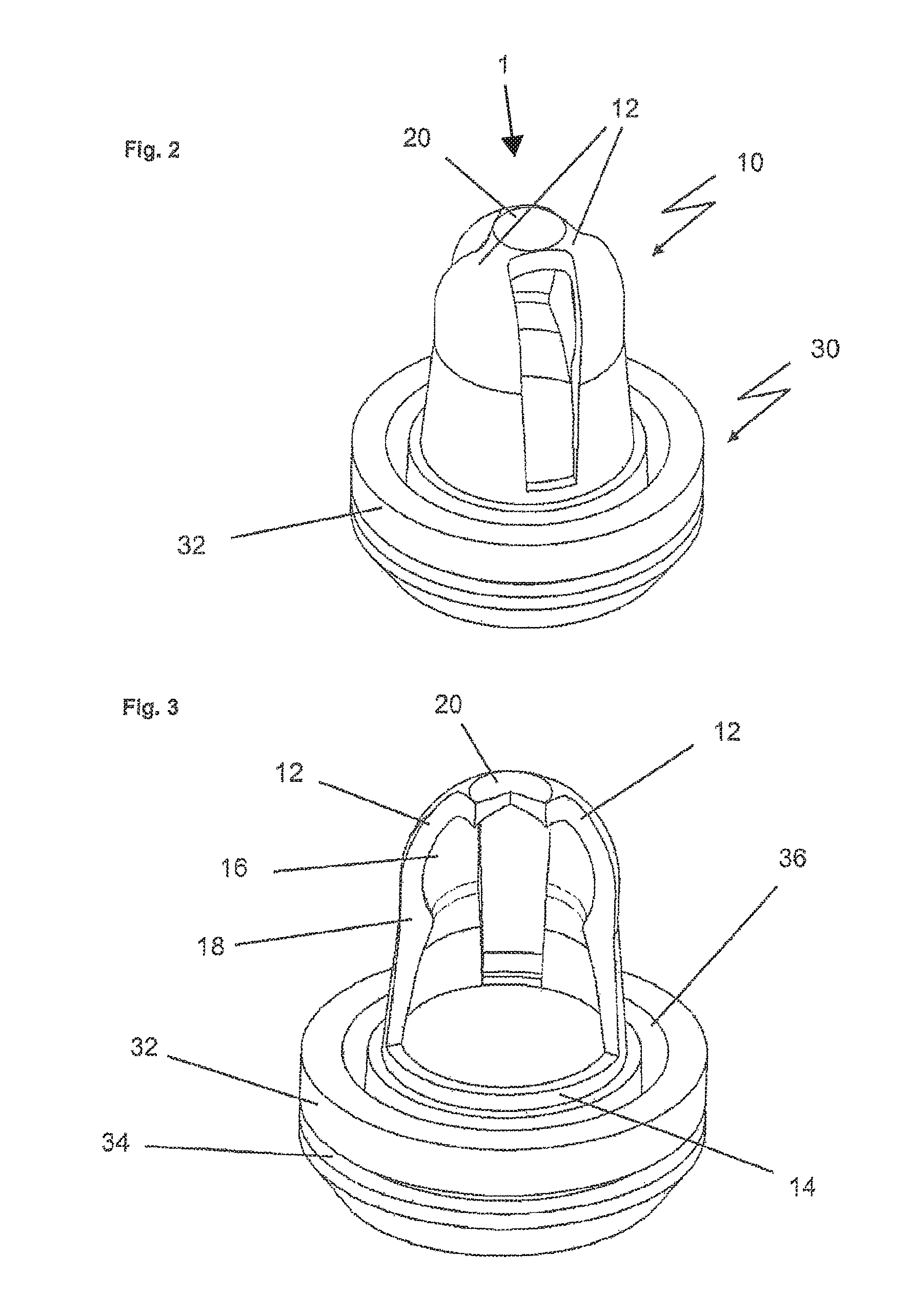
[0028]The plug-in coupling 70 also comprises the negative coupling part 1. It consists of a coupling construction 10 in which the positive coupling part 80 is detachably fastened. According to one embodiment of the present invention, the coupling construction 10 comprises a ball socket, in which the ball head 84 of the above described pin 82 can be accommodated latching detachably. Other shapes, which are formed complementary to the above described positive couplin...


PUM

PropertyMeasurementUnit
elasticityaaaaaaaaaa
elasticaaaaaaaaaa
stabilityaaaaaaaaaa

Abstract

The plug-in coupling comprises a negative coupling part and a positive coupling part that includes a pin having a ball head. The negative coupling part comprises a coupling construction made of a first material for accommodating and detachably fastening the positive coupling part, and a retaining construction made of a second material, which surrounds the coupling construction, for fastening the negative coupling part to the second component, wherein the second material has a higher elasticity than the first material.

Description

FIELD OF THE INVENTION[0001]The present invention relates to a plug-in coupling comprising a negative and positive coupling part, in particular a ball socket as a negative coupling part in combination with a ball pin as a positive coupling part. The present invention further relates to a production method for the negative coupling part of the plug-in coupling.BACKGROUND OF THE INVENTION[0002]Different plug-in couplings are known from the prior art, and are described for example in the documents U.S. Pat. No. 5,580,204, EP 0 902 198 B1, EP 1 746 294 A1, DE 201 17 323 U1, U.S. Pat. Nos. 5,409,302 and 4,904,107.[0003]U.S. Pat. No. 5,580,204 describes a negative coupling part, in particular a ball socket which is produced from plastic. This ball socket has on the outside thereof a circumferential recess and a projecting retaining ring so that the inner wall of an opening of a component can snap into the circumferential recess. In this manner, the ball socket, as a one-piece component ma...

Claims


Application Information

Patent Timeline
Patent Type & Authority Patents(United States)
IPC IPC(8): F16B5/06F16B21/07B29C45/16
CPCF16B5/0621B29C45/16F16B5/065F16B21/073F16B21/078B29C45/1676Y10T403/7039F16B2200/10
Inventor METTEN, ANDREASFRITZSCH, JASMIN
Owner BOLLHOFF VERBINDUNGSTECHNIK GMBH
Why Eureka
Try Eureka