Flexible armored pipe

a flexible armored pipe technology, applied in the direction of flexible pipes, pipes, mechanical equipment, etc., can solve the problems of high axial force on the above type of flexible pipes, and the tendency of the profiles to slide out over each other, and achieve the effect of strong and durable armoring layer and simple production

Inactive Publication Date: 2016-10-04
NAT OILWELL VARCO DENMARK
View PDF66 Cites 4 Cited by
  • Summary
  • Abstract
  • Description
  • Claims
  • Application Information

AI Technical Summary

Benefits of technology

[0010]It is an object of the present invention to provide a flexible pipe with an armor layer comprising a new configuration of helically wound elongate elements that reduces the risk of the elongate elements sliding radially out over each other, while simultaneously being relatively simple to produce and resulting in a strong and durable armoring layer compared to prior art armoring layers of corresponding materials and thickness.

Problems solved by technology

A flexible pipe of the above type will often be subjected to high axial forces due to high pressure on the outer side of the pipe and / or due to high pressure in the bore of the pipe.
Even in situations where an armor layer is made from interlocked profiles, these profiles may have a tendency to slide out over each other with subsequent damage to the pipe.

Method used


Image

  • Flexible armored pipe
  • Flexible armored pipe
  • Flexible armored pipe

Examples


Embodiment Construction

AND DESCRIPTION OF DRAWINGS

[0100]The invention will be explained more fully below in connection with examples and with reference to the drawings.

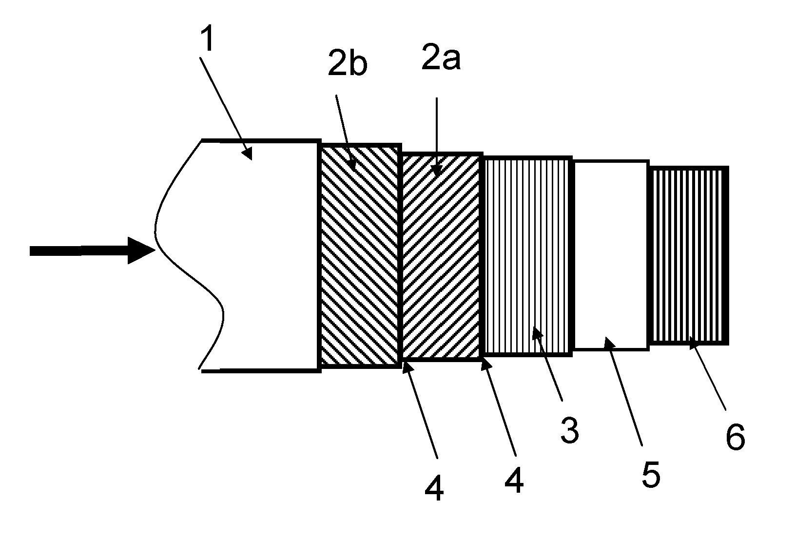
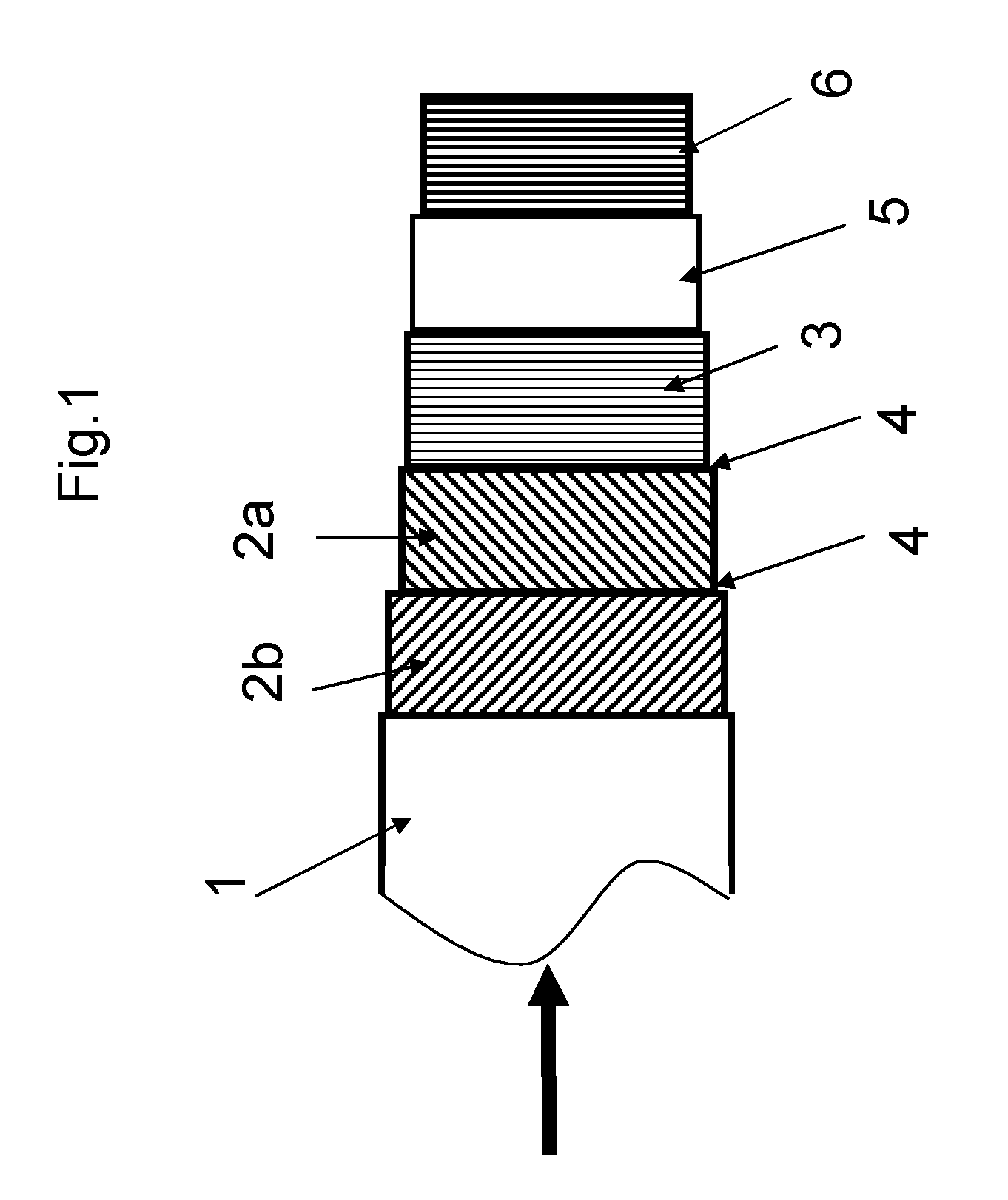
[0101]FIG. 1 is a schematic side view of a flexible armored pipe of the invention.

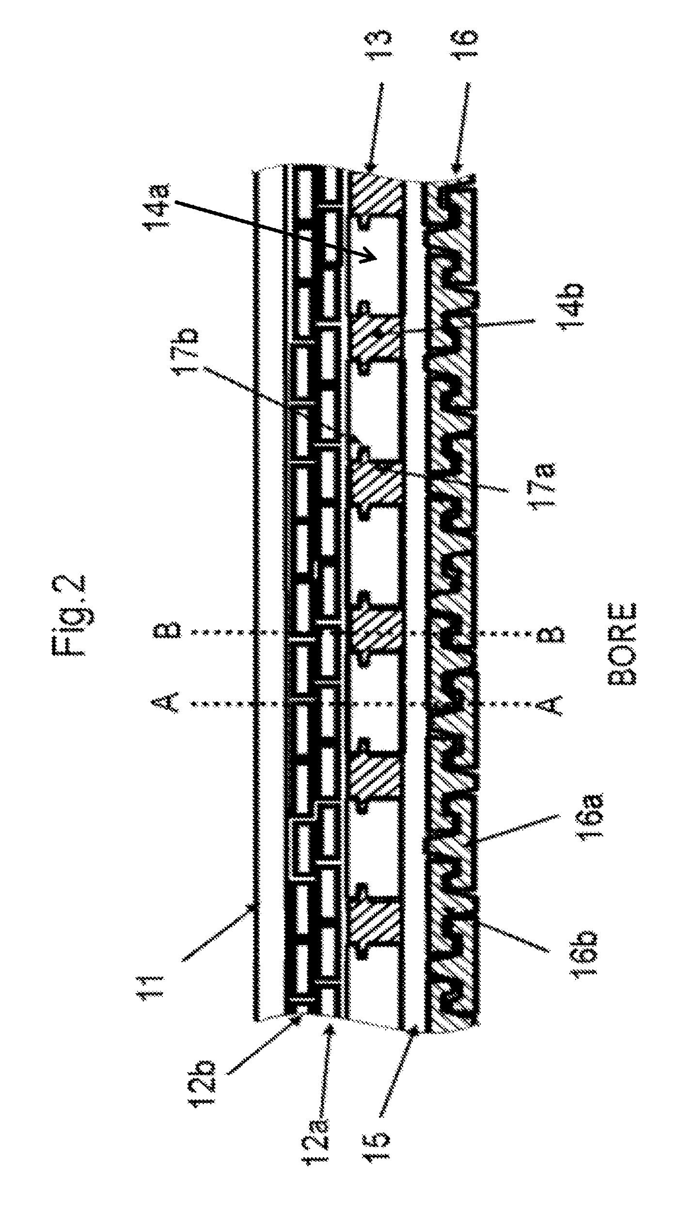
[0102]FIG. 2 is a cross-sectional view along the length of a flexible pipe of the invention where the layers of the pipe can be seen.

[0103]FIG. 3a is a cross-sectional view of a first displacement reduced armor layer where the cross-sectional cut is taken in cross-section of the female type elongate element(s) and the male type elongate element(s).

[0104]FIG. 3b is a cross-sectional view of a variation of the first displacement reduced armor layer where the cross-sectional cut is taken in cross-section of the female type elongate element(s) and the male type elongate element(s).

[0105]FIG. 4 is a cross-sectional view of a second displacement reduced armor layer where the cross-sectional cut is taken in cross-section of the female type elongate element(s) and the...


PUM


Abstract

The invention relates to a flexible armored pipe for transportation of fluids, comprising an inner sealing sheath and at least one displacement reduced armor layer comprising a plurality of elongate elements comprising at least a female type elongate element comprising at least one recess in each opposite side and a male type elongate element comprising at least one protruding tongue in each opposite side and wherein each of the female type and the male type elongate elements are substantially symmetrical in a symmetry line substantially normal to the inner sealing sheath when the pipe is in a non-bended state and where said protruding tongues of said male type elongate element windings are engaged in said recesses of adjacent female type elongate element windings.

Description

TECHNICAL FIELD[0001]The invention relates to a flexible armored pipe and more preferably to an unbonded flexible pipe of the type which can be used for transportation of fluids offshore, such as oil and / or gas fluids.BACKGROUND ART[0002]Flexible pipes of the present type for offshore transportation of fluids are well known in the art and are for example described in “Recommended Practice for Flexible Pipe”, API 17 B, second Edition, 1998, which provides a standard for such pipes. Such pipes usually comprise an inner liner also often called an inner sealing sheath or an inner sheath, which forms a barrier against the outflow of the fluid which is conveyed through the pipe, and one or more armor layers on the outer side of the inner sealing sheath (outer armor layer(s)). Often the flexible pipe also comprises an armor layer on the inner side of the inner sealing sheath, such an armor layer is normally called a carcass and is mainly provided in order to reduce the risk of collapse of ...

Claims


Application Information

Patent Timeline
Patent Type & Authority Patents(United States)
IPC IPC(8): F16L11/00F16L11/08F16L11/16
CPCF16L11/00F16L11/083F16L11/16
Inventor GUDME, JONASGLEJBOL, KRISTIANCAPPELN, CHRISTIAN DITLEV
Owner NAT OILWELL VARCO DENMARK
Why Eureka
Try Eureka