Cleaning device for kitchen appliances and pump systems

a technology for cleaning devices and kitchen appliances, applied in the direction of ovens, heating types, stoves or ranges, etc., can solve the problem of high cost of valves

Active Publication Date: 2016-10-11
HANNING ELECTRO WERKE GMBH & CO KG
View PDF8 Cites 1 Cited by
  • Summary
  • Abstract
  • Description
  • Claims
  • Application Information

AI Technical Summary

Benefits of technology

[0009]The special advantage of the invention is that by providing the drain pump, the liquid can be conveyed actively from the collecting tank, and an operable shut-oil valve in the drain line can be omitted. Only one single hydraulic circuit is formed since the drain pump together with the circulating pump will be associated with the same collecting tank. The liquid can therefore, on one hand, be used for cleaning the cooking space. In this case, the circulating pump conveys the liquid provided in the collecting tank via the circulation line into the cooking space. Preferably, the liquid is delivered against the ventilation fan and is thereby distributed by the ventilation fan. On the other hand, the liquid sitting in the collecting tank can be removed by means of the drain pump and supplied to the drain line. Preferably solids such as lime or other residues are also removed from the collecting tank along with the liquid.
[0010]According to a preferred embodiment of the invention, a riser is provided between the collecting tank and the drain line. The drain pump is dimensioned such that the liquid sitting in the collecting tank together with any solids that may be contained therein can be pumped into the drain line via the riser. Providing the riser ensures that the liquid sitting in the collecting tank does not automatically and unintentionally drain via the drain line despite the common hydraulic circuit for drain pump and circulating pump. The riser is designed in particular such that the liquid for the removal of the same from the collecting tank must be pumped beyond a maximum allowable liquid level of the collecting tank. This ensures that emptying of the collecting tank is realized only when the drain pump is operated. Accordingly, a valve in the drain line can be therefore be omitted.
[0011]Based on a further development of the invention, a non-return valve is provided in the riser. The non-return valve, which is specifically provided in a lower part of the riser or close to the drain pump, prevents any backflow of liquid that is already in the riser from returning to the collecting tank.
[0012]Relative to a horizontal installation position of the cleaning apparatus, the conveyor wheel of the drain pump is preferably provided below the conveyor wheel of the circulating pump. Providing the conveyor wheel of the drain pump below the conveyor wheel of the circulating pump promotes complete or nearly complete emptying of the collecting tank. In addition, any solids that may be present in the liquid will sink to the bottom of the collecting tank and accumulate there. In particular when the liquid in the collecting tank is not circulated. Solids can then be removed by the drain pump which is provided below the circulating pump. In particular, the drain pump can be provided in a horizontal installation position of the collecting tank adjacent to a lower wall of the collecting tank and / or in the vicinity of a sump that defines the lowest point of the collecting tank.
[0013]At the same time, the raised arrangement of the circulating pump wheel relative to the drain pump wheel ensures that liquid preferably with no or few solids is conveyed via the circulation line for the purpose of cleaning the cooking space. In this respect, the circulating pump will at most convey small amounts of solids due to its installation location. Thus, the design counteracts an unintended, renewed contamination of the cooking space.
[0014]According to a further development of the invention, a first conveyor chamber formed as part of the collecting tank for the conveyor wheel of the drain pump and a second conveyor chamber for the conveyor wheel of the circulating pump are provided. The conveyor chambers each have an inlet opening for the liquid and any solids contained therein and an outlet opening. For example, the riser follows the outlet opening of the first conveyor chamber and the circulation line follows the outlet opening of the second conveyor chamber.

Problems solved by technology

For this reason the valve is very expensive.

Method used


Image

  • Cleaning device for kitchen appliances and pump systems
  • Cleaning device for kitchen appliances and pump systems
  • Cleaning device for kitchen appliances and pump systems

Examples


Embodiment Construction

[0035]The preferred embodiments of the present invention will now be described with reference to FIGS. 1-5 of the drawings. Identical elements in the various figures are designated with the same reference numerals.

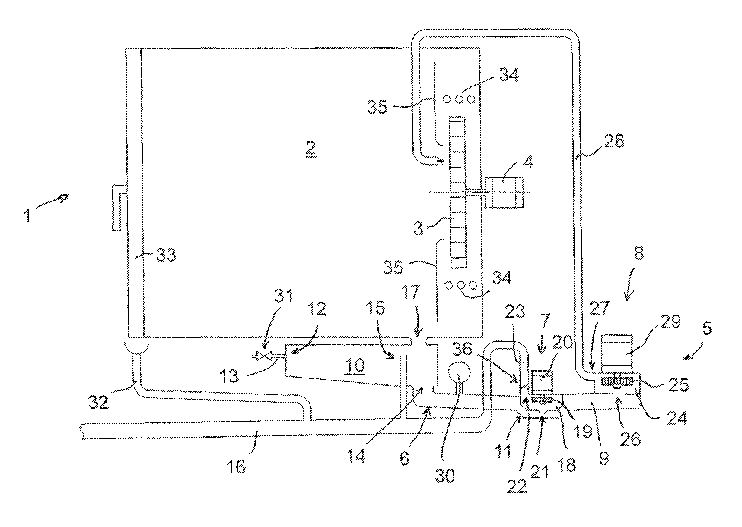
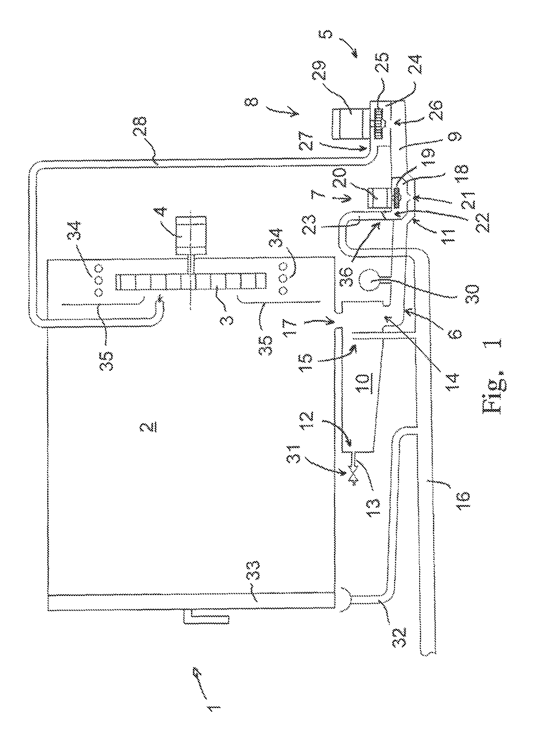
[0036]FIG. 1 shows a schematic representation of an oven. As essential components, the oven comprises a cooking system 1 having a cooking space 2, a ventilation fan 3, which is provided in the cooking space 2 and a drive motor 4 for the ventilation fan 3, a pump system 5 having a collecting tank 6, a drain pump 7, having a circulating pump 8 and various liquid lines 16, 23, 28 as well as a not shown control. A cleaning apparatus for the cooking equipment is realized consisting of the cooking system 1, the pump system 5 and the control which in particular allows for a self-cleaning function of the cooking space 2. A significant feature of the cleaning apparatus is the common hydraulic circuit formed by the collecting tank 6 and the two pumps 7 and 8 which allow for pumping ...


PUM


Abstract

Cleaning apparatus for kitchen equipment, in particular combination streaming, baking and cooking equipment has a cooking space that is to be cleaned which is delimited by at least one wall and includes at least one outlet opening for a liquid. The apparatus comprises a ventilation fan associated with the cooking space having a drive motor; a collecting tank which at least temporarily collects the liquid that exits the cooking space via the outlet opening; a supply line that can be used to supply fresh water and / or a cleaning fluid that can be controlled through a valve in the line; a circulating pump provided at the collecting tank for the liquid sitting in the collecting tank; a circulation line by which the liquid sitting in the collecting tank and conveyed by the circulating pump can be supplied to the cooking space and a drain line for discharging the liquid that exits the cooking space. A drain pump is provided at the circulation container in addition to the circulating pump which is able to actively convey the liquid sitting in the collecting tank, together with solids that may be present therein, into the drain line.

Description

BACKGROUND OF THE INVENTION[0001]The invention relates to a cleaning apparatus for kitchen equipment, in particular combination steamer, baking and / or cooking equipment having a cooking space to be cleaned that is delimited by at least one wall. The cooking space has at least one outlet opening for a liquid, a ventilation fan with a drive motor, and a collecting tank which at least temporarily collects the liquid that exits the cooking space via the outlet opening. A supply line is provided to supply fresh water and / or cleaning fluid, under control of a valve, to the cooking space. A circulating pump is provided for the liquid collected in the collecting tank with a circulation line by which the liquid, sitting in the collecting tank, can be conveyed to the cooking space. The apparatus also has a drain line for discharging the liquid that exits the cooking space.[0002]Furthermore, the invention relates to a pump system that can be used, in particular, for a cleaning apparatus accord...

Claims


Application Information

Patent Timeline
Patent Type & Authority Patents(United States)
IPC IPC(8): A21B3/00F04B41/06F04B23/04F04B23/02B08B9/00A47L15/00F24C14/00
CPCF24C14/005A21B3/006A47L15/0097F04B23/02F04B23/04F04B41/06B08B9/00
Inventor HANGMANN, WERNERPFLUG, THOMASEVERT, CHRISTIAN
Owner HANNING ELECTRO WERKE GMBH & CO KG
Why Eureka
Try Eureka