

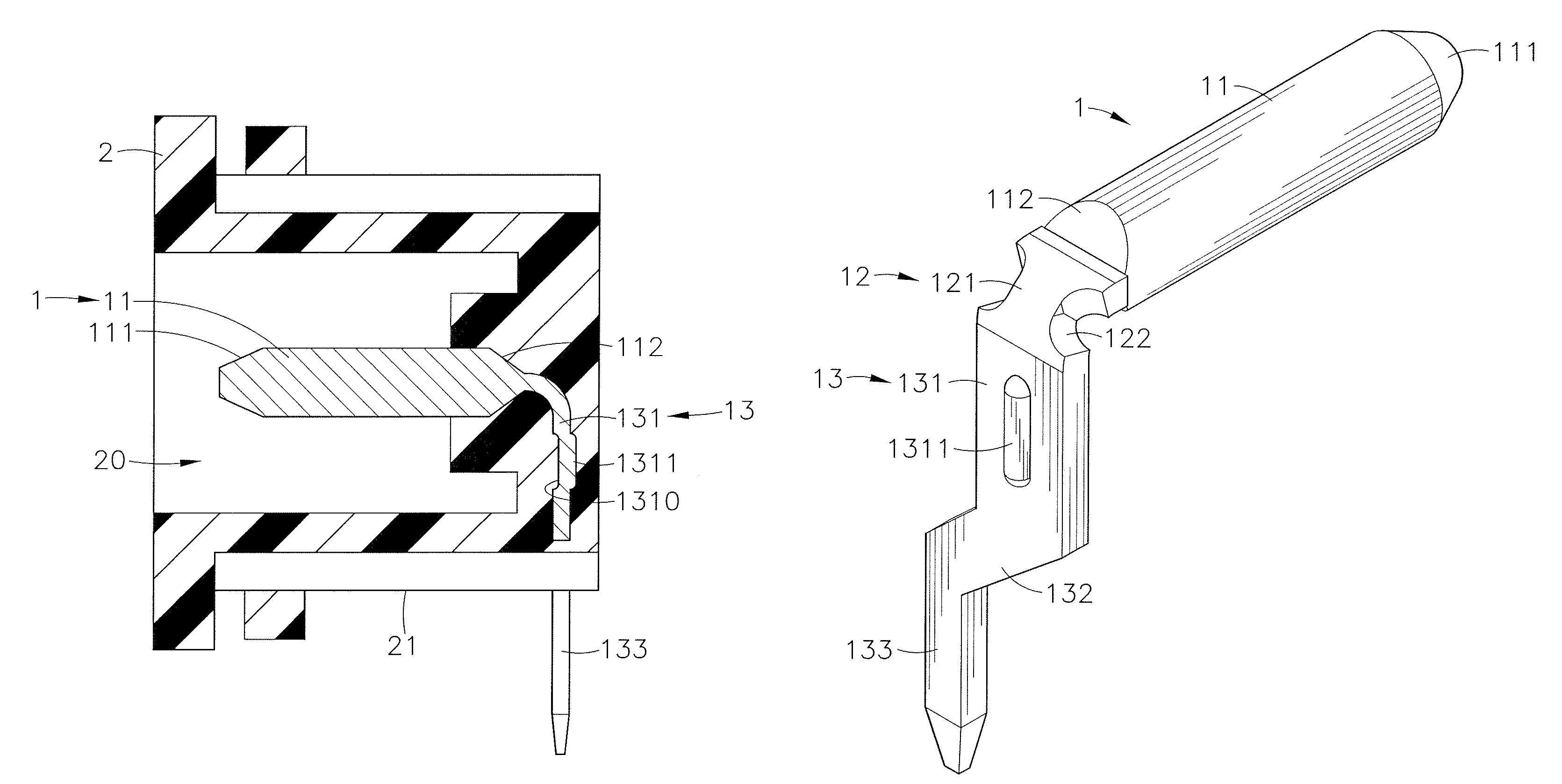
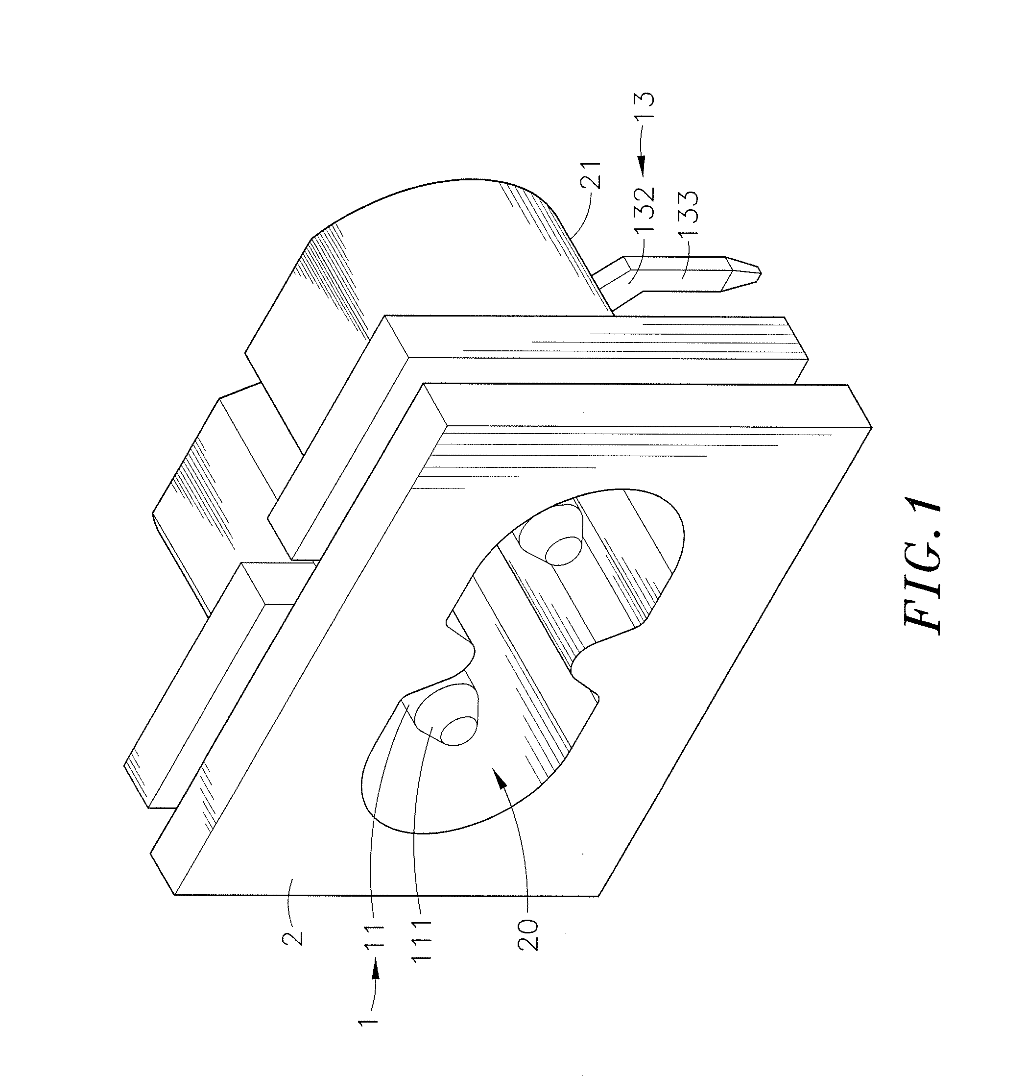
Electric connector having terminals with outwardly extending extension arms
a technology of electric connectors and extension arms, which is applied in the manufacture of contact members, coupling device connections, contact member assembly/disassembly, etc., can solve the problems of poor contact, degradation of the yield rate of electric connectors, complex manufacturing process, etc., and achieves enhanced endurability of electric connectors, reduced stress concentration, and increased yield rate of terminals.
- Summary
- Abstract
- Description
- Claims
- Application Information
AI Technical Summary
Benefits of technology
Problems solved by technology
Method used
Image


Examples
Embodiment Construction
[0020]Reference will now be made in detail to the exemplary embodiments of the present disclosure, examples of which are illustrated in the accompanying drawings. Therefore, it is to be understood that the foregoing is illustrative of exemplary embodiments and is not to be construed as limited to the specific embodiments disclosed, and that modifications to the disclosed exemplary embodiments, as well as other exemplary embodiments, are intended to be included within the scope of the appended claims. These embodiments are provided so that this disclosure will be thorough and complete, and will fully convey the inventive concept to those skilled in the art. The relative proportions and ratios of elements in the drawings may be exaggerated or diminished in size for the sake of clarity and convenience in the drawings, and such arbitrary proportions are only illustrative and not limiting in any way. The same reference numbers are used in the drawings and the description to refer to the ...
PUM
 Abstract
Description
Claims
Application Information