Steering system

a steering system and steering wheel technology, applied in the direction of steering parts, vehicle components, transportation and packaging, etc., can solve the problem of not being able to achieve reliable locking sta

Active Publication Date: 2016-10-18
JTEKT CORP
View PDF20 Cites 15 Cited by
  • Summary
  • Abstract
  • Description
  • Claims
  • Application Information

AI Technical Summary

Benefits of technology

[0008]It is an object of the present invention to provide a steering system that is capable of achieving strong lock and preventing occurrence of half lock while suppressing an increase in number of components.

Problems solved by technology

However, so-called “half lock” in which the top portions of the teeth contact each other is occasionally caused.
In the case where half lock is caused, a reliable locked state is not achieved.

Method used


Image

  • Steering system
  • Steering system
  • Steering system

Examples


Embodiment Construction

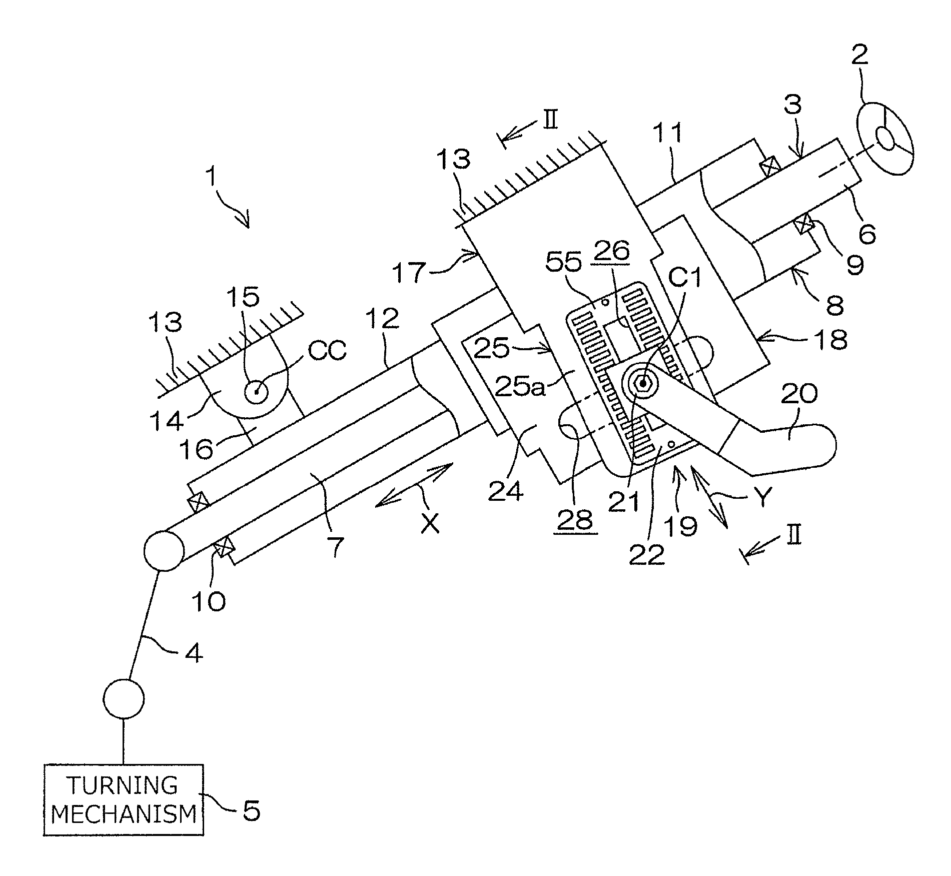
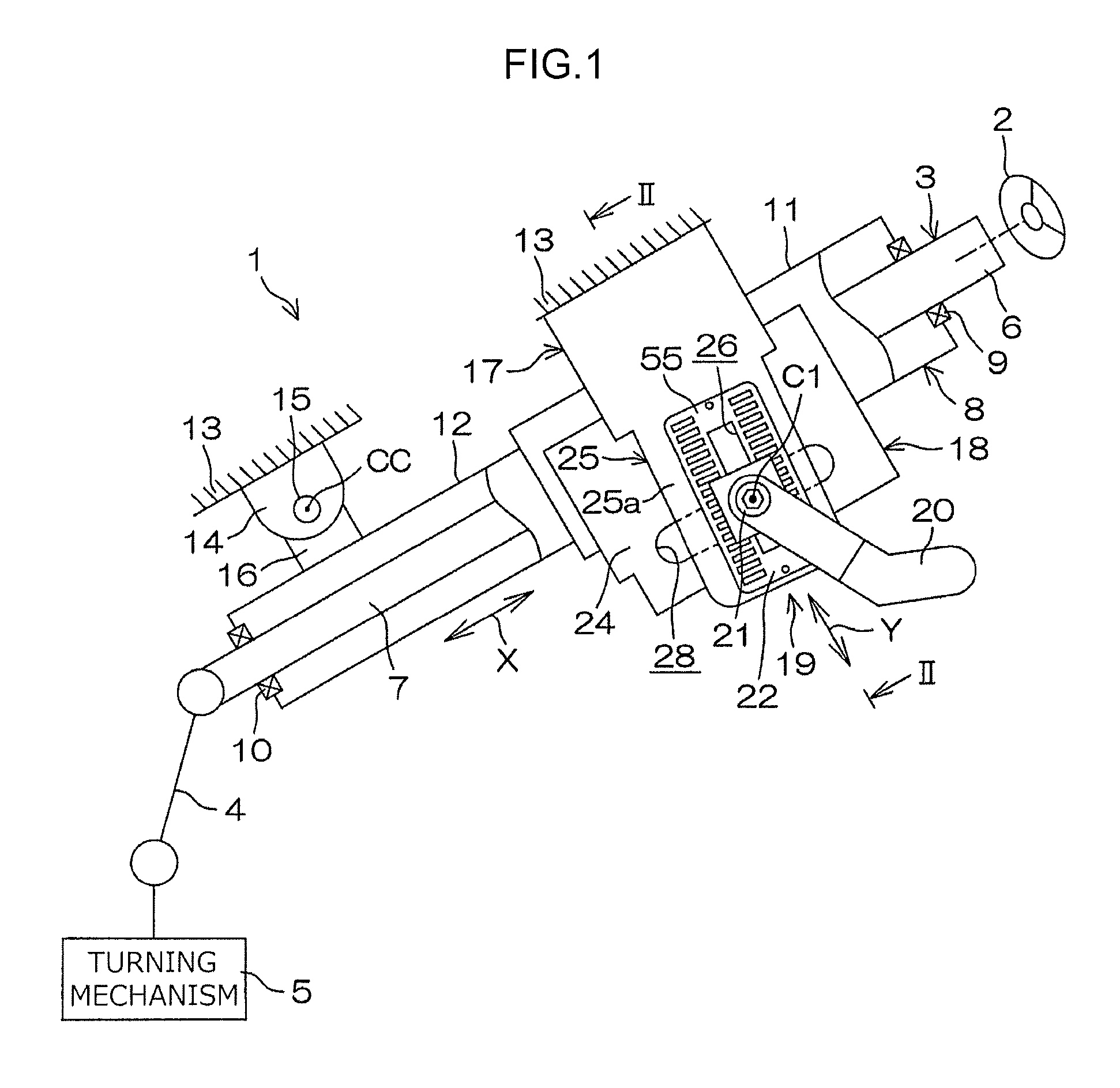
[0033]An embodiment of the present invention will be described in detail below with reference to the accompanying drawings. FIG. 1 is a partially cut-away, schematic side view illustrating a schematic configuration of a steering system 1 according to a first embodiment of the present invention. With reference to FIG. 1, the steering system 1 includes a steering shaft 3 and a turning mechanism 5. A steering member 2 such as a steering wheel is coupled to one end of the steering shaft 3 in an axial direction X. The turning mechanism 5 is coupled to the steering shaft 3 via an intermediate shaft 4 etc.

[0034]The turning mechanism 5 is a rack-and-pinion mechanism, for example, that turns turning wheels (not illustrated) in conjunction with a steering operation of the steering member 2. Rotation of the steering member 2 is transferred to the turning mechanism 5 via the steering shaft 3, the intermediate shaft 4, etc. Rotation transferred to the turning mechanism 5 is converted into axial ...


PUM


Abstract

A lock device of a steering system includes a tongue piece unit and a frame plate held on a first side plate. The tongue piece unit includes elastic tongue pieces supported in a cantilever manner by a vertical frame provided along at least one of longitudinal edge portions of at least one of first side plates to form a row that extends in a tilt direction. The frame plate includes partitioning portions, between which a plurality of grooves are formed to house the elastic tongue pieces so as to be projectable. When a steering column is locked, some of the elastic tongue pieces are pressed by a pressing surface of a tightening member to be retracted into grooves. Consequently, the tightening member is interposed between the elastic tongue pieces projecting from the grooves in the tilt direction.

Description

INCORPORATION BY REFERENCE[0001]The disclosure of Japanese Patent Application No. 2014-127227 filed on Jun. 20, 2014 including the specification, drawings and abstract, is incorporated herein by reference in its entirety.BACKGROUND OF THE INVENTION[0002]1. Field of the Invention[0003]The present invention relates to a steering system.[0004]2. Description of the Related Art[0005]Hitherto, it has been attempted, in a lock device that locks a steering column in position after tilt adjustment, to achieve strong lock by meshing teeth provided on a fixed member and teeth provided on a movable member with each other. However, so-called “half lock” in which the top portions of the teeth contact each other is occasionally caused. In the case where half lock is caused, a reliable locked state is not achieved.[0006]Japanese Patent Application Publication No. 2008-49830 (JP 2008-49830 A) proposes a lock device that includes a plurality of plate members, a push-in member, and an urging member. T...

Claims


Application Information

Patent Timeline
Patent Type & Authority Patents(United States)
IPC IPC(8): B62D1/184B62D1/185B62D1/189
CPCB62D1/184B62D1/185B62D1/189
Inventor TANAKA, HIDENOBUYOSHIHARA, YOSHIHITONAGATANI, ATSUMUNE
Owner JTEKT CORP
Why Eureka
Try Eureka