Radically curable compound, method for producing radically curable compound, radically curable composition, cured product of the same, and resist-material composition

a technology of radically curable compounds and compounds, applied in the direction of organic chemistry, coatings, chemistry apparatus and processes, etc., can solve the problems of difficult application of thermal nanoimprint lithography to the electric and electronic field, difficult use of polymer resins having a high glass transition temperature, and cracking at the interface between solder resist and sealing resins, etc., to achieve high heat resistance, high heat resistance, and high heat resistance

Active Publication Date: 2016-10-18
DIC CORPORATION
View PDF7 Cites 0 Cited by
  • Summary
  • Abstract
  • Description
  • Claims
  • Application Information

AI Technical Summary

Benefits of technology

[0008]The inventors of the present invention performed thorough studies. As a result, the inventors have found, for example, the following findings: a cured product has very high heat resistance, the cured product being obtained by curing a compound having a structure that is provided by a reaction between a trifunctional phenol having a specific structure and a (meth)acrylic acid halide; and such a method allows easy production of the compound. Thus, the inventors have accomplished the present invention.
[0018]A radically curable compound according to the present invention can provide a cured product having heat resistance on a very high level. Accordingly, a radically curable compound according to the present invention can be used as a solder resist material and a material for nanoimprinting that are required to have high heat resistance. A radically curable compound according to the present invention is a material that is photo-curable and can be used to form a shape by light and hence can also be used for a material for a mold of the thermal nanoimprint lithography. In a case where a thermoplastic resin used as resist in the thermal nanoimprint lithography is a high-heat-resistant electric / electronic-material engineering plastic having a glass transition temperature (Tg) of more than 200° C. such as polyphenylene ether (PPE), this plastic is subjected to a softening treatment at a temperature of 300° C. or more. In this case, a cured product of a radically curable compound according to the present invention has very high heat resistance and hence can be used as a material for the mold.

Problems solved by technology

Build-up boards and the like having fine wiring therein still have a problem in that cracking occurs at the interface between solder resist and sealing resin, which is referred to as popcorning.
However, the thermal nanoimprint lithography requires softening of such a polymer resin by heating and polymer resins having a high glass transition temperature are difficult to use.
Thus, the thermal nanoimprint lithography is difficult to apply to the electric and electronic field in which higher heat resistance has been required in recent years.
However, these resins do not have the high heat resistance that has been required in recent years.

Method used


Image

  • Radically curable compound, method for producing radically curable compound, radically curable composition, cured product of the same, and resist-material composition
  • Radically curable compound, method for producing radically curable compound, radically curable composition, cured product of the same, and resist-material composition
  • Radically curable compound, method for producing radically curable compound, radically curable composition, cured product of the same, and resist-material composition

Examples


synthesis example 1

Synthesis of Polycondensate (A-1)

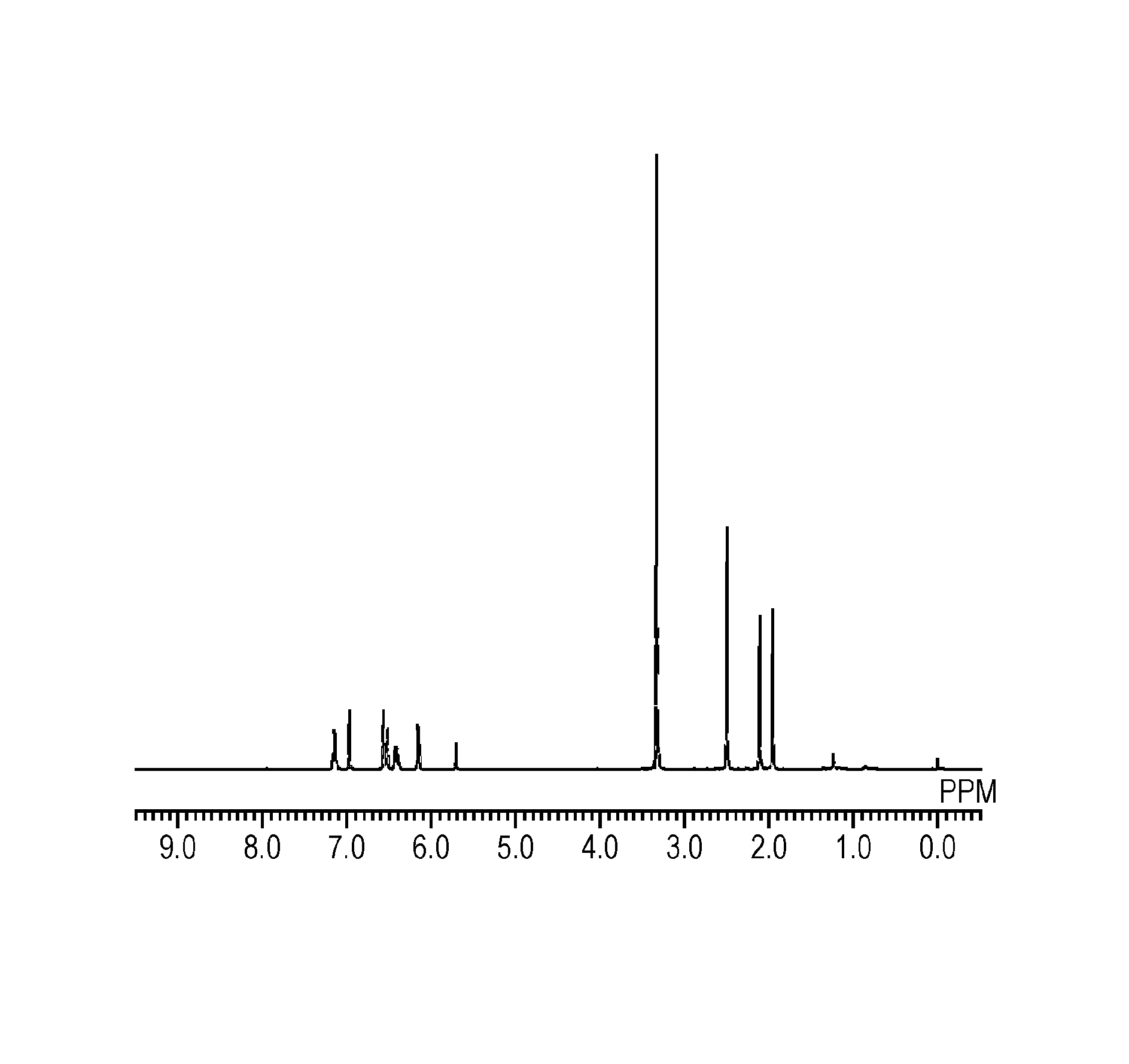
[0105]To a 100-ml two-neck flask equipped with a condenser, 7.32 g (60 mmol) of 2,5-xylenol and 2.44 g (20 mmol) of 4-hydroxybenzaldehyde were charged and dissolved in 20 ml of 2-ethoxyethanol. To this solution being cooled in an ice bath, 2 ml of sulfuric acid was added. The resultant solution was heated and stirred in an oil bath at 100° C. for 2 hours to thereby cause a reaction. After the reaction, the resultant solution was subjected to a reprecipitation process with water to provide a crude product. The crude product was dissolved again in acetone and subjected to a reprecipitation process with water. The resultant product was isolated by filtration and subjected to vacuum drying. This provided 5.93 g of a polycondensate (A-1) having a molecular structure represented by a formula (5-1) below. The purity of the polycondensate (A-1) in the crude product was 87% by mass on the basis of GPC area ratio. The purity of the polycondensate (A-1) finally...

example 1

Synthesis of Radically Curable Compound

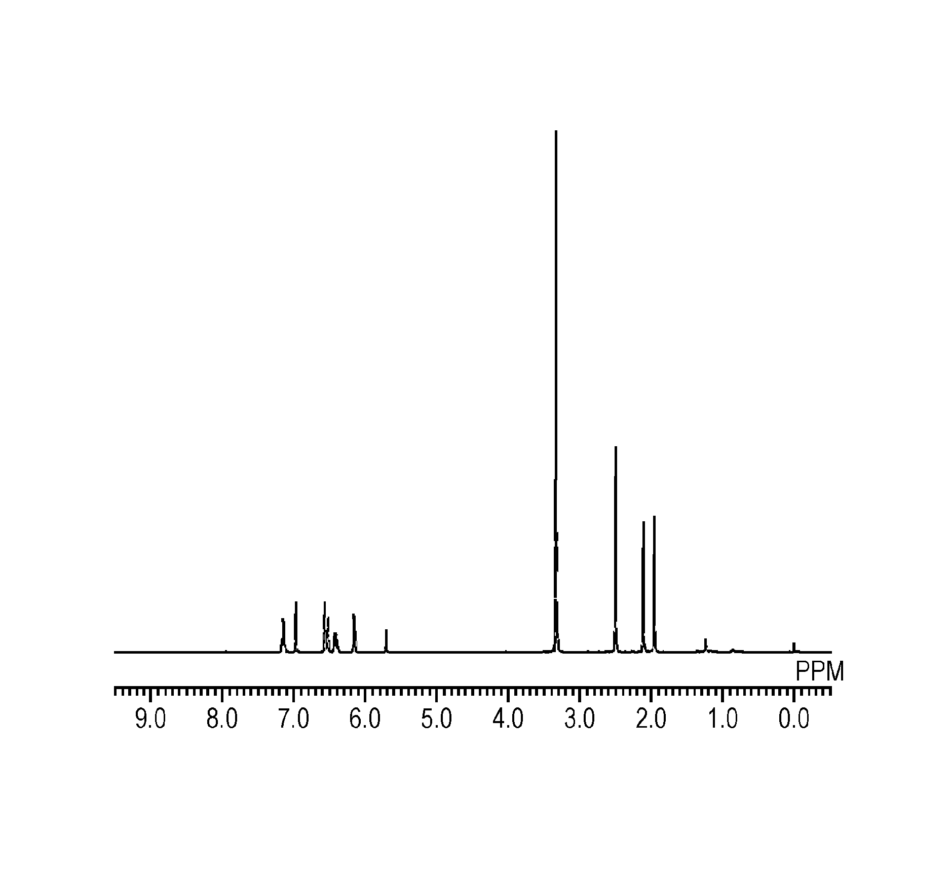
[0107]To a 100-ml two-neck flask equipped with a condenser, 1.74 g (5 mmol) of the polycondensate (A-1), 4.10 g (30 mmol) of potassium carbonate, and 10 ml of tetrahydrofuran were charged and stirring was initiated. To this solution being cooled in an ice bath, 3.60 g (20 mmol) of acryloyl chloride was added dropwise over 30 minutes. The resultant solution was heated and stirred in an oil bath at 70° C. for 12 hours to thereby cause a reaction. After the reaction, solid content was separated from the resultant solution by filtration; the filtrate was mixed with 30 ml of chloroform and washed three times with 50 ml of water. The underlying organic layer was separated and dried over sodium sulfate. After that, the solvent was distilled off under a reduced pressure to provide 1.79 g of a radically curable compound (1) that was white acicular crystals. This compound was identified on the basis of peaks of 1H-NMR and it was confirmed that the compou...


PUM

PropertyMeasurementUnit
temperatureaaaaaaaaaa
Tgaaaaaaaaaa
temperatureaaaaaaaaaa

Abstract

Provided is a positive photoresist composition excellent in terms of heat resistance. A radically curable compound is represented by a general formula (1) below (where R1, R2, and R3 each independently represent an alkyl group having 1 to 8 carbon atoms; m and n each independently represent an integer of 1 to 4; p represents an integer of 0 to 4; X, Y, and Z each independently represent an acryloyloxy group, a methacryloyloxy group, or a hydroxy group, and at least one of X, Y, and Z represents an acryloyloxy group or a methacryloyloxy group; and t represents 1 or 2).

Description

TECHNICAL FIELD[0001]The present invention relates to a radically curable compound that provides a cured product excellent in terms of heat resistance.BACKGROUND ART[0002]In recent years, electronic devices have undergone remarkable technical advances and integrated circuits having a higher density and higher performance have been rapidly developed. In response to such developments, printed wiring boards have come to have a higher density, more highly integrated wiring, and surface-mounted components. Such printed wiring boards also need to have a higher accuracy and higher performance than before. In response to such developments of integrated circuits having a higher density and higher performance, there have been studies on improvements in the performance of solder resist serving as a main material of integrated circuits. Build-up boards and the like having fine wiring therein still have a problem in that cracking occurs at the interface between solder resist and sealing resin, w...

Claims


Application Information

Patent Timeline
Patent Type & Authority Patents(United States)
IPC IPC(8): C08L69/00C08G8/30C08F222/10C07C37/20C07C37/00C08F22/14C09D4/00C07C69/54C07C67/14
CPCC07C69/54C07C37/002C07C37/20C07C67/14C08F22/14C08F222/1006C08G8/30C09D4/00C07C39/16C08F20/20C08F20/30
Inventor IMADA, TOMOYUKIKAGE, TAKAKAZUSHIN, DONGMI
Owner DIC CORPORATION
Why Eureka
Try Eureka