Torque coupler

a technology of torque couplers and couplers, applied in the direction of yielding couplings, springs/dampers, rotational vibration suppression, etc., can solve the problem of increasing construction space, and achieve the effect of increasing loading capacity

a technology of torque couplers and couplers, applied in the direction of yielding couplings, springs/dampers, rotational vibration suppression, etc., can solve the problem of increasing construction space, and achieve the effect of increasing loading capacity

US9470290B2Active Publication Date: 2016-10-18SCHAEFFLER TECH AG & CO KG

Image

  • Torque coupler
  • Torque coupler
  • Torque coupler

Examples


Embodiment Construction

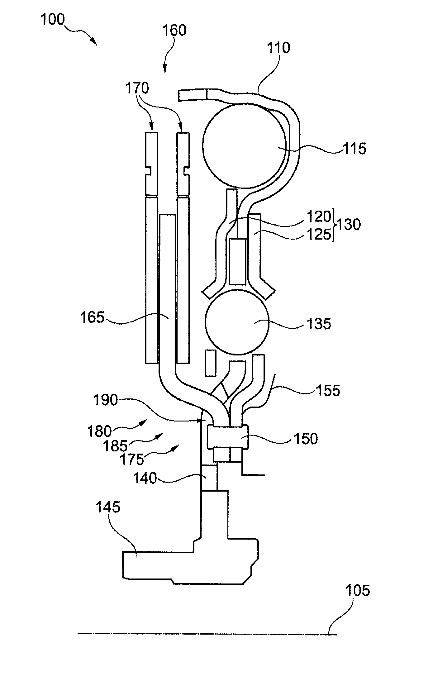
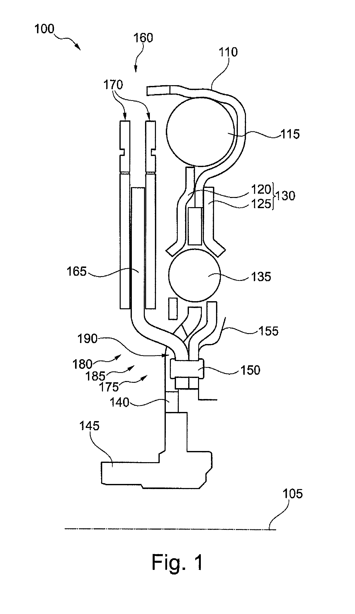
[0020]FIG. 1 shows a sectional view of a torque coupler 100. The depiction shows only the upper half of a longitudinal section through an axis of rotation 105, around which the elements of the torque coupler 100 are rotatably positioned.

[0021]The depicted torque coupler 100 includes a retainer 110 for connecting to an input side to introduce a torque, a first elastic element 115, a first (here left-side) plate element 120 and a second (here right-side) plate element 120, the plate elements 120 and 125 being enclosed by an intermediate plate 130; also a second elastic element 135, an output flange 140, a hub 145, a connecting element 150, a turbine 155 merely suggested in FIG. 1, as well as a centrifugal force pendulum 160, which includes a pendulum flange 165 and a pendulum mass 170.

[0022]Not all of the named components of the torque coupler 100 are absolutely necessary. The focal point of the present invention is the attachment of the pendulum flange 165 to the intermediate plate 1...


PUM


Abstract

A torque coupler includes an input side and an output side, which are situated rotatably around an axis of rotation, and in addition an intermediate plate for coupling with the input side, an output flange for coupling with the output side, a spring damper for coupling the intermediate plate with the output flange, and a centrifugal force pendulum having a pendulum flange and a pendulum mass. Here the pendulum flange extends between a first area, in which the pendulum flange is attached to the intermediate plate, and a second area, in which the pendulum mass is attached to the pendulum flange. The output flange has a cutout, through which a section of the pendulum flange which connects the two areas runs.

Description

[0001]The invention relates to a torque coupler, in particular for use in a drivetrain of a motor vehicle.BACKGROUND[0002]A torque coupler is used to transmit torque in a drivetrain of a motor vehicle. On the one hand, the torque coupler provides a torsional connection of an output shaft of a drive motor to a drive shaft of a transmission, and, on the other hand, it is set up to damp or cancel out torsional vibrations that are superimposed on the transmitted torque. To that end, the torque coupler includes a spring damper and a centrifugal force pendulum. The spring damper includes an elastic element whose ends are connected to an input side or an output side of the torque coupler, in order to compress or to decompress the spring damper under the influence of a changing torque. The centrifugal force pendulum includes a pendulum flange, on which a pendulum mass is movably situated in the plane of rotation, so that the pendulum mass is moved radially inward or outward under the influe...

Claims


Application Information

Patent Timeline
18 Oct 2016
Publication
US9470290B2
IPC
F16F15/123; F16D3/66; F16F15/14; F16F15/134
CPC
F16F15/145; F16D3/66; F16F15/13484
Inventors
HOFFMANN, JAN