
Torque coupler

a technology of torque couplers and couplers, applied in the direction of yielding couplings, springs/dampers, vibration suppression adjustments, etc., can solve the problem of increasing construction space and achieve the effect of increasing loading capacity

Active Publication Date: 2015-07-23
SCHAEFFLER TECH AG & CO KG
View PDF8 Cites 0 Cited by
  • Summary
  • Abstract
  • Description
  • Claims
  • Application Information

AI Technical Summary

Benefits of technology

The patent describes a torque coupler that reduces bending loads and increases the life of connections, while also allowing for a more compact design and cost savings. The coupler includes a pendulum flange that can be brought closer to an intermediate plate, allowing for a rivet or bolt connection with reduced axial leverage. The attachment of the pendulum flange to the intermediate plate can take place in cohesive friction, reducing the bending loading on the connection. The coupler also includes a cutout that protects the elastic element of the spring damper from overloading and allows for a more compact design. The pendulum flange can be cranked and attached to the output flange in an optimal manner. Additionally, the coupler may also include a turbine that is attached to the intermediate plate by a common connecting element, which increases the loading capacity of the attachment.

Problems solved by technology

Because of the reduced loading, the connection can also be dimensioned more weakly, which may result in cost benefits, and additional construction space can be gained in the area of the connection.

Method used


Image

  • Torque coupler
  • Torque coupler
  • Torque coupler

Examples


Embodiment Construction

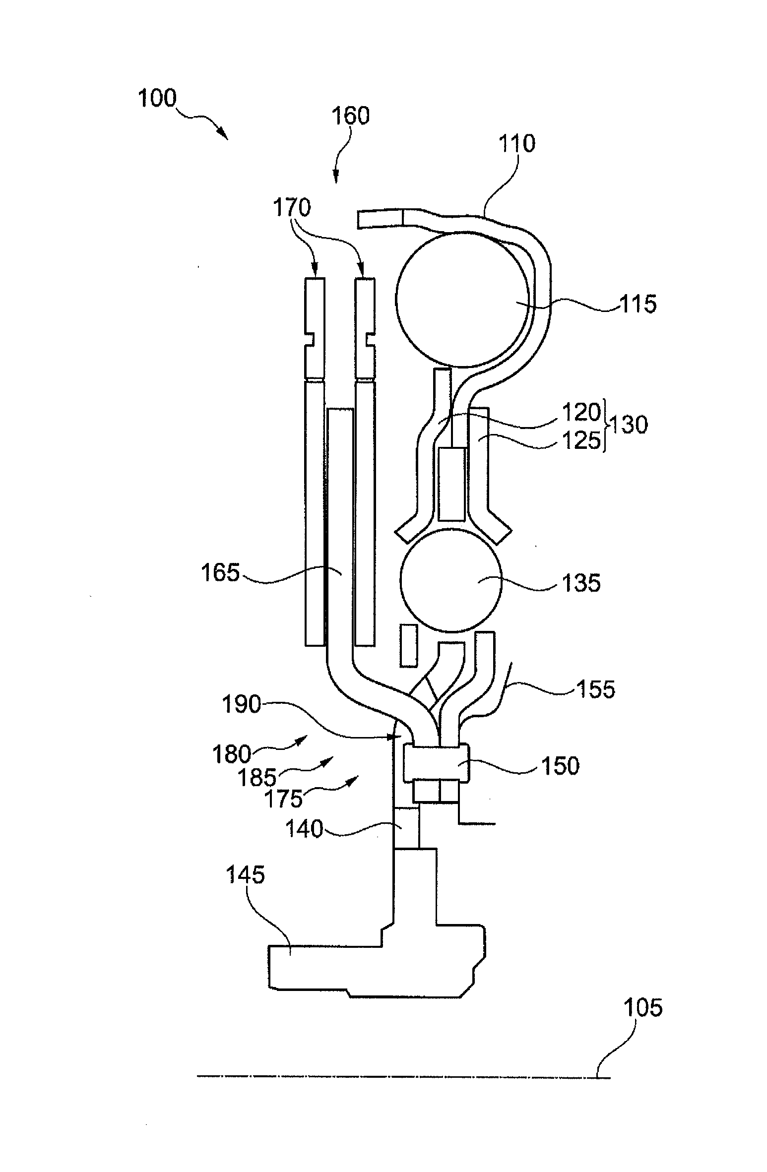
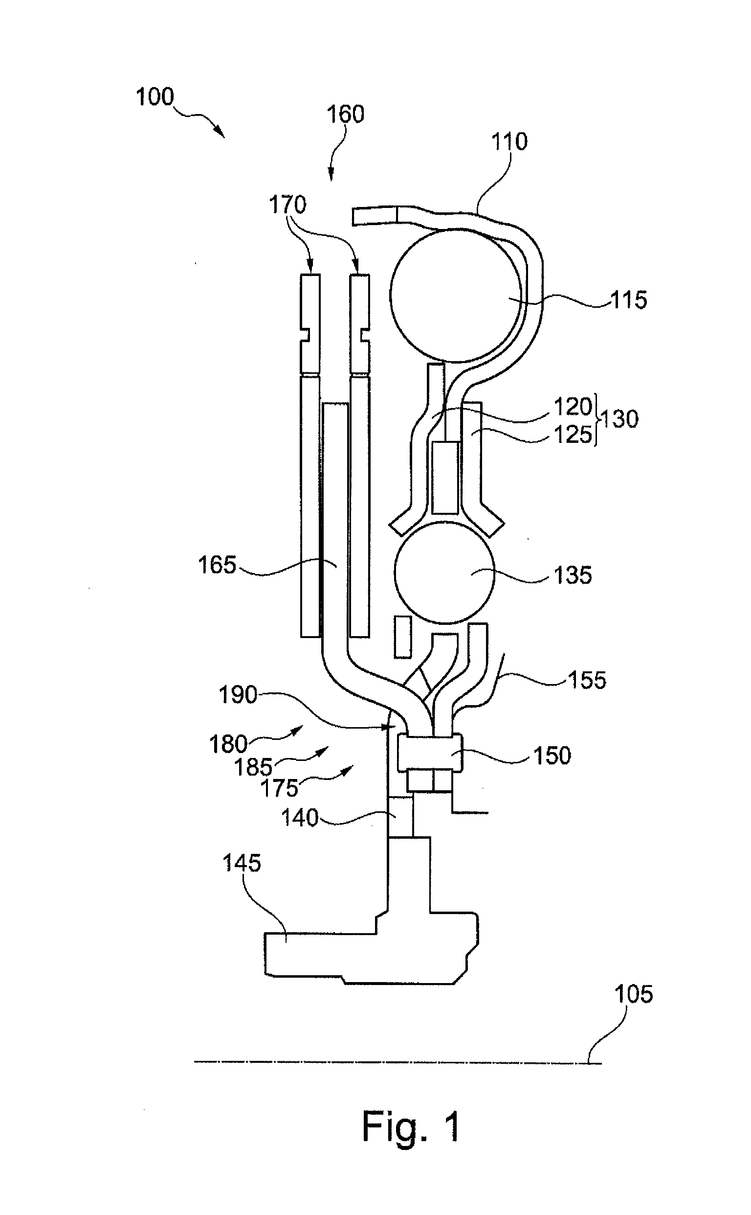
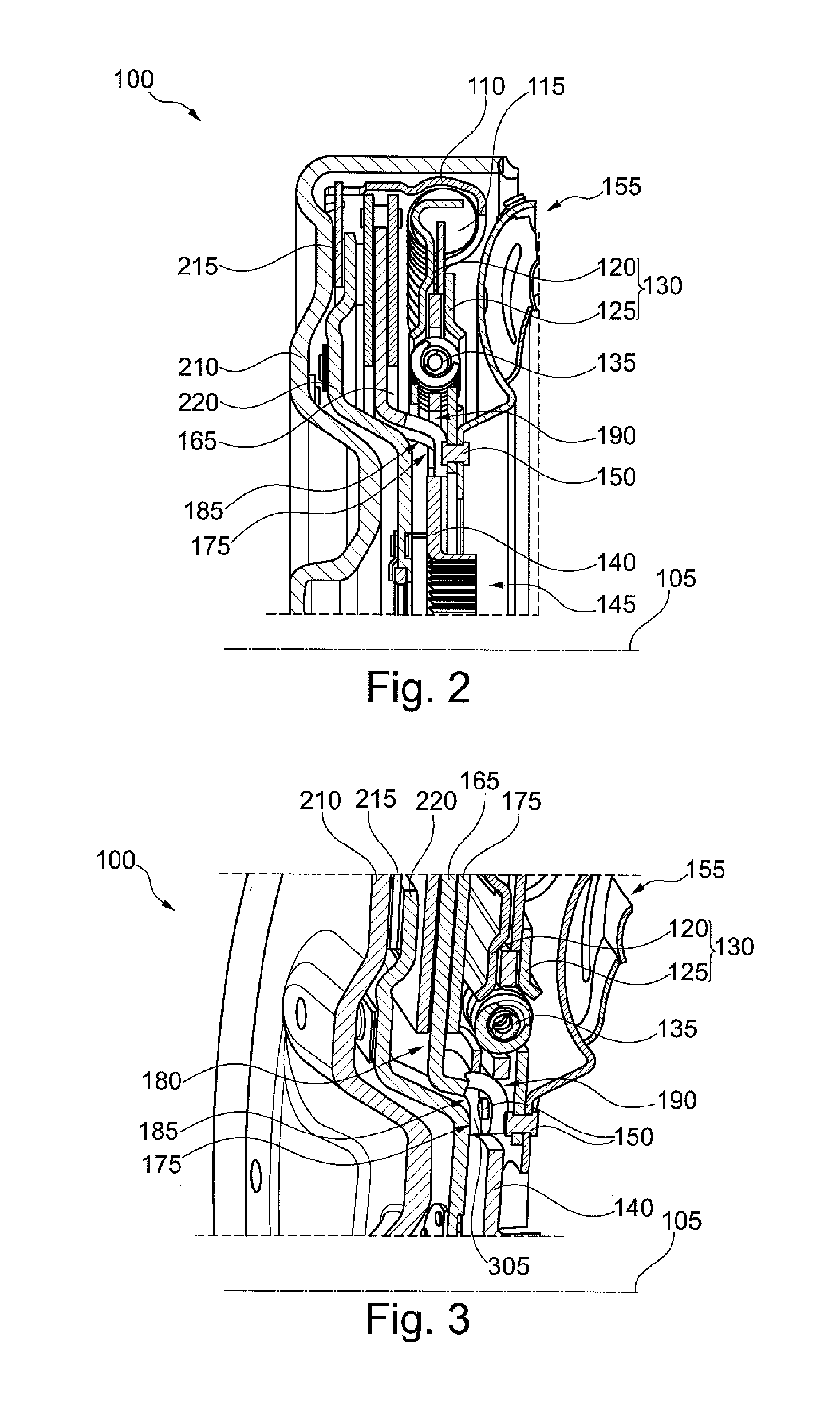
[0020]FIG. 1 shows a sectional view of a torque coupler 100. The depiction shows only the upper half of a longitudinal section through an axis of rotation 105, around which the elements of the torque coupler 100 are rotatably positioned.

[0021]The depicted torque coupler 100 includes a retainer 110 for connecting to an input side to introduce a torque, a first elastic element 115, a first (here left-side) plate element 120 and a second (here right-side) plate element 120, the plate elements 115 and 120 being enclosed by an intermediate plate 130; also a second elastic element 135, an output flange 140, a hub 145, a connecting element 150, a turbine 155 merely suggested in FIG. 1, as well as a centrifugal force pendulum 160, which includes a pendulum flange 165 and a pendulum mass 170.

[0022]Not all of the named components of the torque coupler 100 are absolutely necessary. The focal point of the present invention is the attachment of the pendulum flange 165 to the intermediate plate 1...


PUM


Abstract

A torque coupler includes an input side and an output side, which are situated rotatably around an axis of rotation, and in addition an intermediate plate for coupling with the input side, an output flange for coupling with the output side, a spring damper for coupling the intermediate plate with the output flange, and a centrifugal force pendulum having a pendulum flange and a pendulum mass. Here the pendulum flange extends between a first area, in which the pendulum flange is attached to the intermediate plate, and a second area, in which the pendulum mass is attached to the pendulum flange. The output flange has a cutout, through which a section of the pendulum flange which connects the two areas runs.

Description

[0001]The invention relates to a torque coupler, in particular for use in a drivetrain of a motor vehicle.BACKGROUND[0002]A torque coupler is used to transmit torque in a drivetrain of a motor vehicle. On the one hand, the torque coupler provides a torsional connection of an output shaft of a drive motor to a drive shaft of a transmission, and, on the other hand, it is set up to damp or cancel out torsional vibrations that are superimposed on the transmitted torque. To that end, the torque coupler includes a spring damper and a centrifugal force pendulum. The spring damper includes an elastic element whose ends are connected to an input side or an output side of the torque coupler, in order to compress or to decompress the spring damper under the influence of a changing torque. The centrifugal force pendulum includes a pendulum flange, on which a pendulum mass is movably situated in the plane of rotation, so that the pendulum mass is moved radially inward or outward under the influe...

Claims


Application Information

Patent Timeline
IPC IPC(8): F16F15/14F16D3/66F16F15/134
CPCF16F15/145F16D3/66F16F15/13484
Inventor HOFFMANN, JAN
Owner SCHAEFFLER TECH AG & CO KG
Learn More