Servo control device reducing deflection of front end point of machine

a technology of servo control and front end point, which is applied in the direction of electric programme control, program control, instruments, etc., can solve the problems of “deflection” or “torsion” to occur, the front end point of the machine is moved with respect, and it is difficult to arrange a detector at the tool front end part or other position close to the front end point of the machine, so as to reduce the “deflection” or “torsion”. the effect of small deflection

Active Publication Date: 2016-10-18
FANUC LTD
View PDF11 Cites 1 Cited by
  • Summary
  • Abstract
  • Description
  • Claims
  • Application Information

AI Technical Summary

Benefits of technology

[0010]The present invention has as its object the provision of a servo control device which combines a control method using feedback and a control method using feedforward to thereby reduce “deflection” or “torsion” of a front end point of a machine to reduce error of movement of the front end point of the machine with respect to a command even with normal commands.
[0012]According to the servo control device of the embodiment of the present invention, it is possible to arrange an acceleration sensor close to the front end point of the machine, estimate the “deflection” or “torsion” of the front end point of the machine from the feedback, and use the results of estimation and the command which is given to the motor to adaptively determine the coefficient of higher order feedforward control so as to make the “deflection” or “torsion” smaller by using the least square method, the steepest descent method, or other method. This higher order feedforward control acts so as to restrict the acceleration of the command. Consequently, it is possible to decrease the “deflection” or “torsion”.

Problems solved by technology

In such a system, when the rigidities of the motor and the front end point of the machine are low, there is a problem that elastic deformation of the machine causes “deflection” or “torsion” to occur and error arises in the movement of the front end point of the machine with respect to a command.
However, in general, it is difficult to arrange a detector at the tool front end part or other position close to the front end point of the machine.
Therefore, there is a problem that the learning control is not usable with normal commands.

Method used


Image

  • Servo control device reducing deflection of front end point of machine
  • Servo control device reducing deflection of front end point of machine
  • Servo control device reducing deflection of front end point of machine

Examples


first embodiment

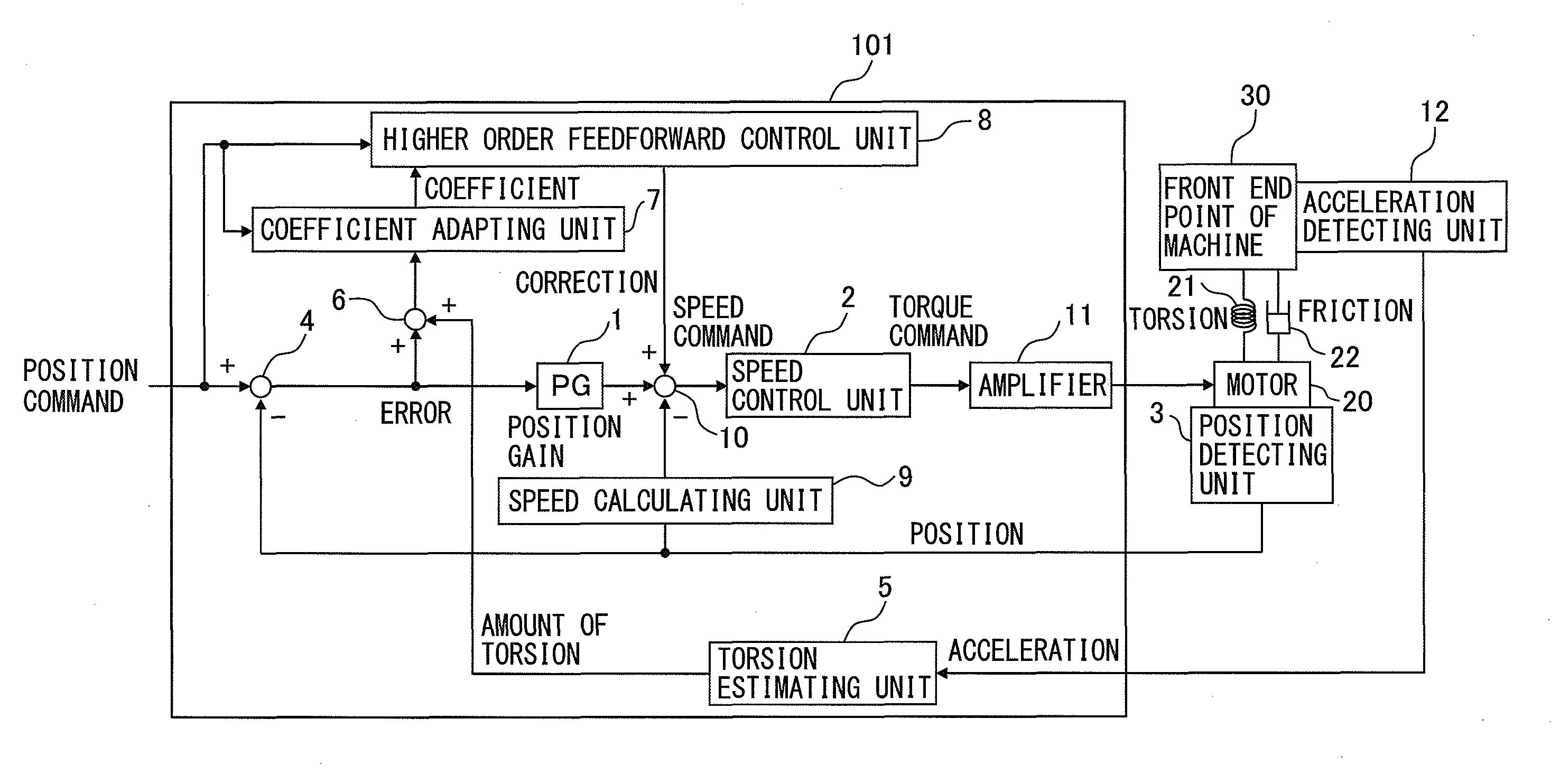
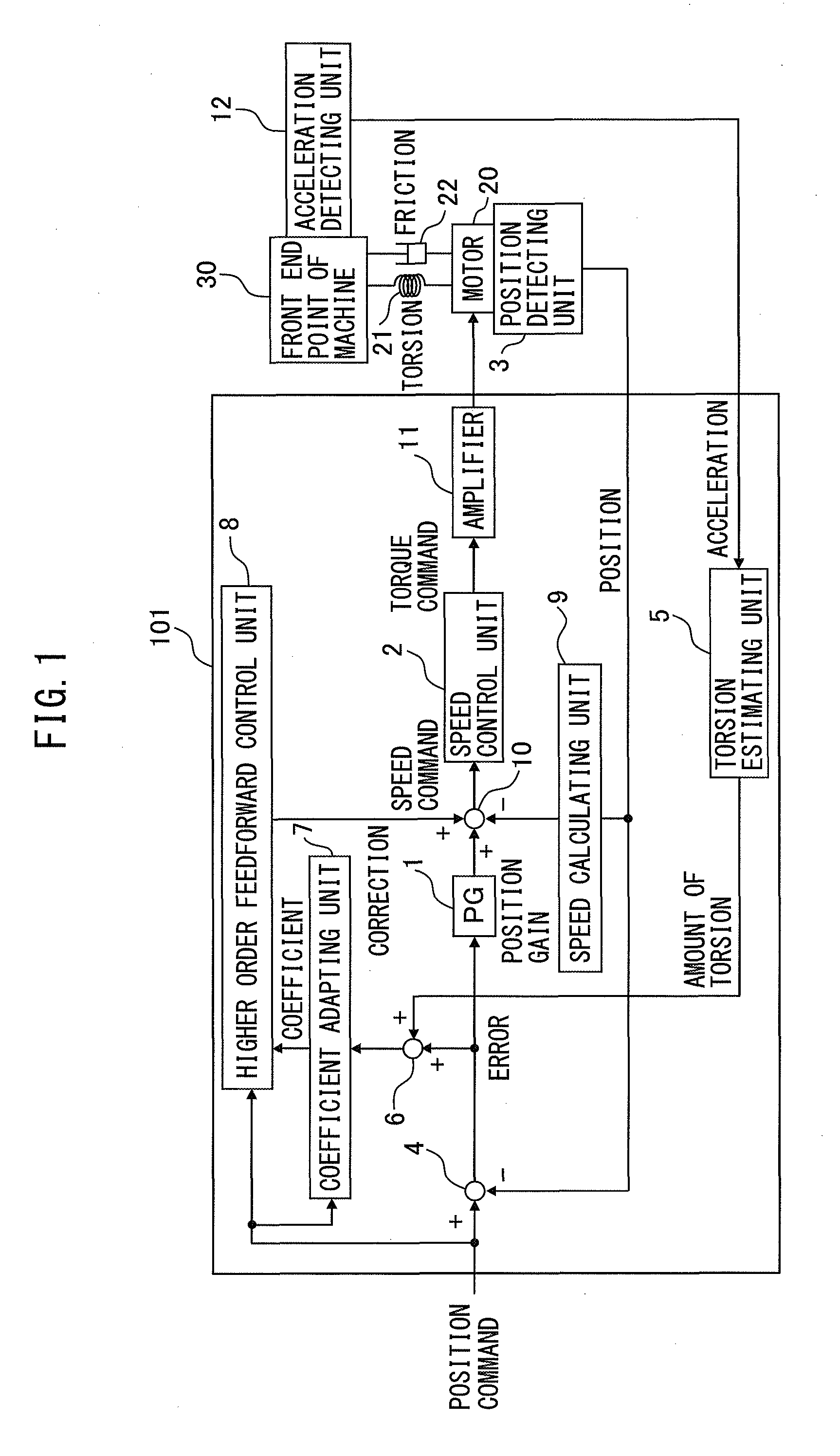
[0025]A servo control device according to a first embodiment of the present invention will be explained using the drawings. FIG. 1 is a configuration diagram of a servo control device according to the first embodiment of the present invention. The servo control device 101 according to the first embodiment of the present invention is a control device which is provided with a position control unit 1 and speed control unit 2 and which controls the position and speed of the motor 20 to control the front end point of the machine 30 of a machine tool. The servo control device 101 is provided with a position detecting unit 3, a first position error calculating unit 4, a torsion estimating unit 5, a second position error calculating unit 6, a coefficient adapting unit 7, and a higher order feedforward control unit 8.

[0026]The control object, that is, the front end point of the machine 30, is controlled by the motor 20. The torsion 21 and the friction 22 must also be considered. The position...

second embodiment

[0051]Next, a servo control device according to a second embodiment of the present invention will be explained using the drawings. FIG. 4 is a configuration diagram of a servo control device according to the second embodiment of the present invention. The servo control device 102 according to the second embodiment differs from the servo control device 101 according to the first embodiment on the point of being provided with, instead of the acceleration detecting unit 12, a speed detecting unit 13 which detects the speed of the motor 20 and a current detecting unit 14 which detects the current of the motor 20. The torsion estimating unit 5 estimates the amount of torsion of the front end point of the machine 30 from the speed of the motor 20 and the current of the motor 20. The rest of the configuration of the servo control device 102 according to the second embodiment is similar to the configuration of the servo control device 101 according to the first embodiment, therefore a detai...

third embodiment

[0084]Next, a servo control device 103 according to a third embodiment of the present invention will be explained using the drawings. FIG. 8 is a configuration diagram of a servo control device 103 according to the third embodiment of the present invention. The servo control device 103 according to the third embodiment differs from the servo control device 101 according to the first embodiment on the point of being provided with, instead of the acceleration detecting unit 12, a speed detecting unit 13′ which detects the speed of the motor 20 and the torsion estimating unit 5 estimates the amount of torsion of the front end point of the machine 30 from the speed of the motor 20 and the torque command to the motor 20. The rest of the configuration of the servo control device 103 according to the third embodiment is similar to the configuration of the servo control device 101 according to the first embodiment, and therefore a detailed description will be omitted.

[0085]Next, the operati...


PUM


Abstract

A servo control device having a position control unit and a speed control unit to control a front end point of a machine of a machine tool, comprising: a position detecting unit for detecting a position of a motor; a first position error calculating unit for calculating a first position error based on a position command to a motor and position feedback from the position detecting unit; a torsion estimating unit for estimating an amount of torsion of the front end point of the machine; a second position error calculating unit for adding the first position error and estimated amount of torsion to calculate a second position error; a coefficient adapting unit for determining a coefficient of feedforward control so as to minimize the second position error; and a higher order feedforward control unit for performing feedforward control by using the determined coefficient and the position command.

Description

BACKGROUND OF THE INVENTION[0001]1. Field of the Invention[0002]The present invention relates to a servo control device which controls a machine tool or other machine which uses a motor, in particular a servo control device which reduces the “deflection” of a processing point when using a tool to process a workpiece, that is, a front end part of the tool (a front end point of the machine), as a driven member which the motor drives.[0003]2. Description of the Related Art[0004]In general machine tools etc., as control systems for axes which are driven by motors, there are semi-closed systems which use detectors which are provided at motors for control and full-closed systems which have separate detectors close to the front end parts of the tools (hereinbelow, referred to as the “front end points of the machines”).[0005]In general, due to cost demands, the former semi-closed systems are more frequently used. In such a system, when the rigidities of the motor and the front end point of ...

Claims


Application Information

Patent Timeline
Patent Type & Authority Patents(United States)
IPC IPC(8): H02P6/00G05B19/404G05B19/19
CPCG05B19/404G05B19/19G05B2219/41139
Inventor SONODA, NAOTO
Owner FANUC LTD
Why Eureka
Try Eureka