
Roll-forming machine and method for roll-forming

a technology of rolling mill and rolling mill, which is applied in the direction of rolling mill stand, multiple strand roll mill stand, manufacturing tools, etc., can solve the problem that the rolling mill cannot be used in the vehicle industry to produce beams with complicated profiles

Active Publication Date: 2016-10-25
ORTIC 3D AB
View PDF10 Cites 1 Cited by
  • Summary
  • Abstract
  • Description
  • Claims
  • Application Information

AI Technical Summary

Benefits of technology

The present invention is a roll-forming machine that can create profiles with complicated shapes, such as beams. Additionally, it is flexible in the sense that manufacturing of different shapes is possible. The machine includes a frame with a tiltable upper part and a displaceable intermediate piece, which increases flexibility and allows for greater influence of the forming station on the material being roll-formed. The axle pins of the rollers are vertically movable, which results in the possibility to vary the material shaping influence of each pair of rollers independently, further broadening the possible shapes obtainable for profiles. The forming stations have mutual movability, allowing for maximum variation of shapes, but some restrictions may be necessary to reduce costs.

Problems solved by technology

However, such a roll-forming machine may not be used within the vehicle industry for producing beams having a complicated profile, such as a beam to be arranged above the wind shield of a vehicle, which is often bent in two planes in a double-bent shape.

Method used


Image

  • Roll-forming machine and method for roll-forming
  • Roll-forming machine and method for roll-forming
  • Roll-forming machine and method for roll-forming

Examples


Embodiment Construction

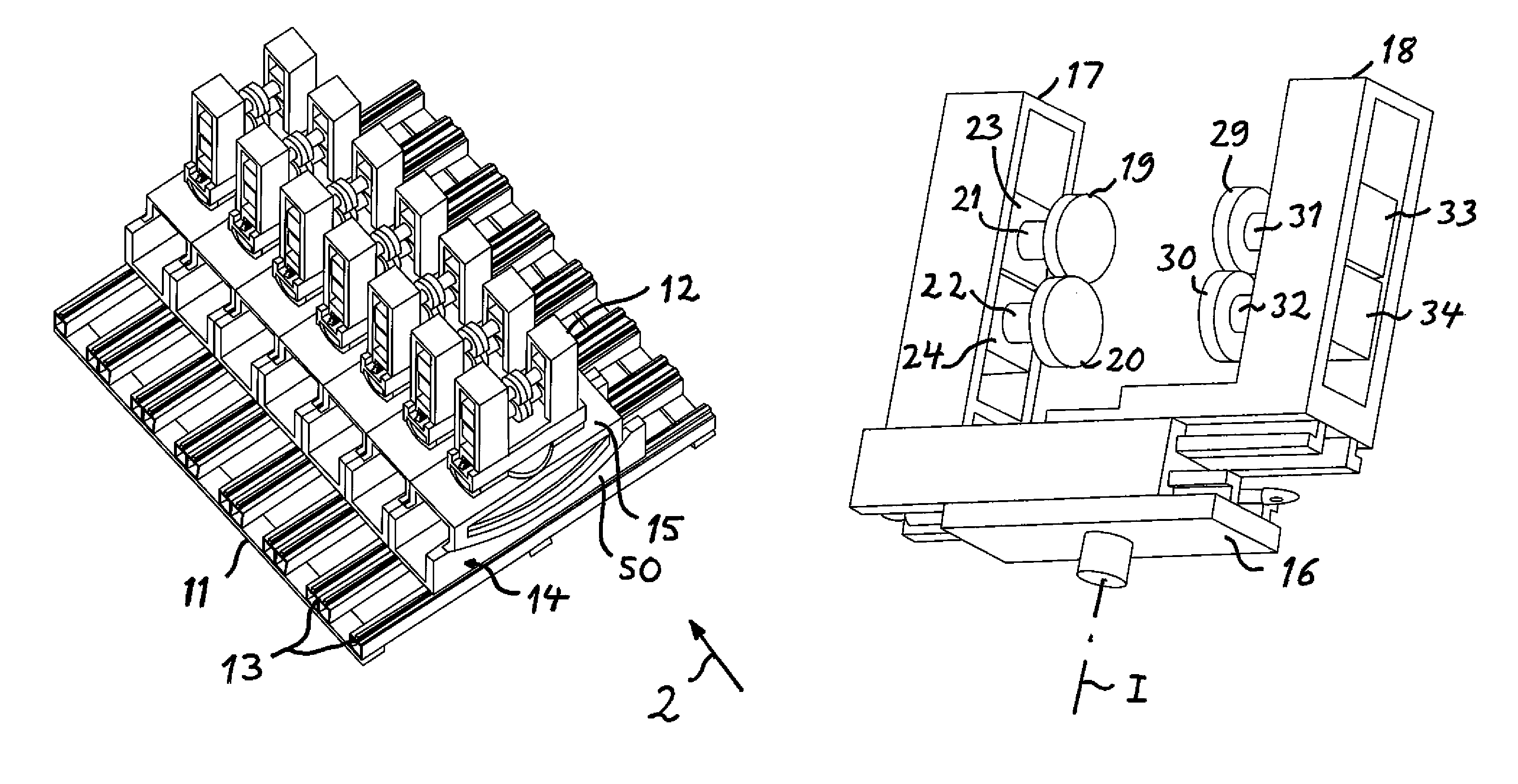
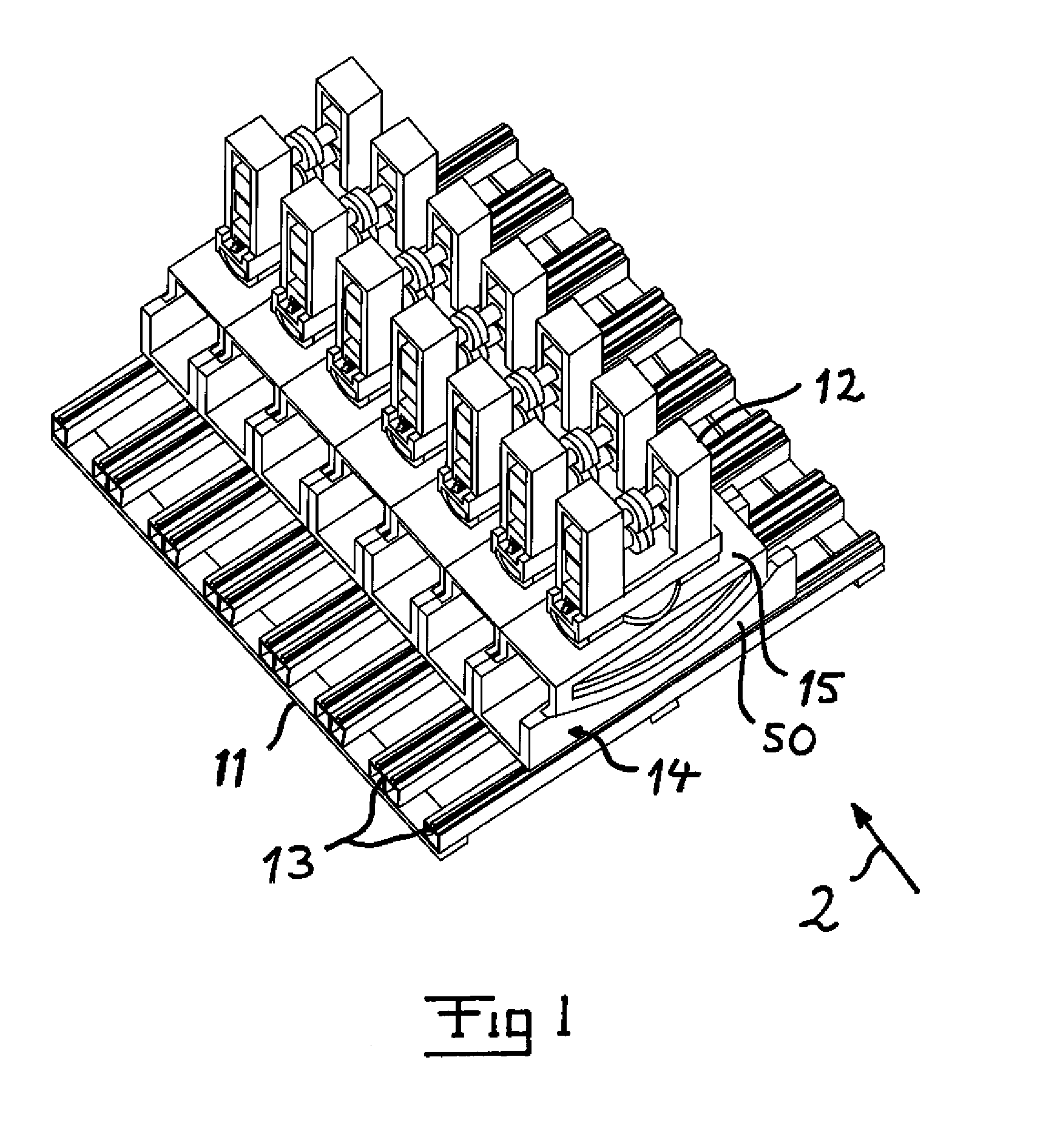
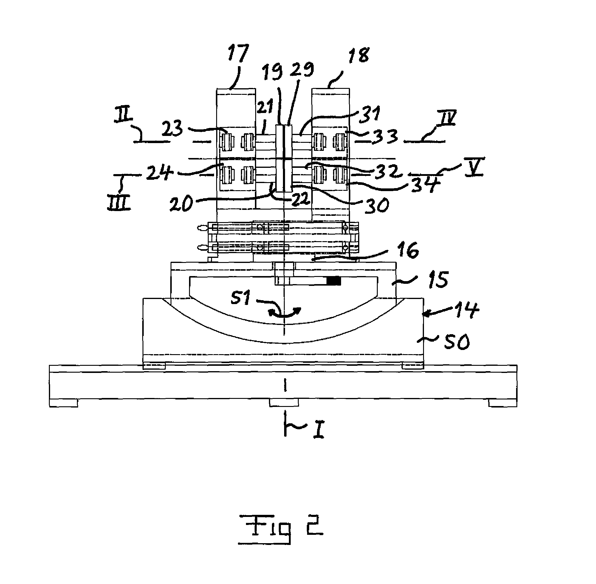
[0026]FIG. 1 shows very schematically the first roll-forming stations of a roll-forming machine according to the invention. The roll-forming stations are arranged in a row so as to successively form a material piece, such as a sheet metal strip, moving through the machine along said row. Such a machine has then normally a considerably higher number of roll-forming stations than shown, such as for example 15-30 such stations, but the invention is not restricted to any particular number of forming stations of the machine. Power means for achieving the movements to be described below of different parts of the machine have been omitted in the figures for simplifying the views and better illustrating other parts of the machine. These power means are advantageously electric motors for enabling a control of the movements of the parts with a high accuracy, but it is also within the scope of the invention to use other types of power means, such as controlled through pneumatic or hydraulic.

[0...


PUM

PropertyMeasurementUnit
anglesaaaaaaaaaa
forming anglesaaaaaaaaaa
strengthaaaaaaaaaa

Abstract

A roll-forming machine has a stand (11) and a row of forming stations (12), which comprise frames (14, 15) for carriers (17, 18) of pair of rollers laterally displaceably mounted on the stand. An intermediate piece (16) is pivotally mounted on each frame for being pivoted about a vertical axis, and two carriers of a pair of rollers are separately laterally displaceably mounted on each intermediate piece. Each carrier of a pair of rollers comprises two axle pins for carrying a forming roller each and the two carriers of a pair of rollers have their axle pins directed towards each other.

Description

FIELD OF THE INVENTION[0001]The invention relates to a roll-forming machine comprising a stand and a row of forming stations comprising frames for carriers of pair of rollers being laterally displaceably mounted on the stand. The invention also relates to a method for roll-forming a sheet metal strip by driving the sheet metal strip through a row of forming stations having pairs of rollers directed towards each other and both holding the sheet metal strip therebetween and form the sheet metal strip over roller edges.[0002]“Laterally” means that the frames are displaceable in lateral direction with respect to the extension of said row of forming stations along which a sheet metal strip to be roll-formed is intended to be fed through the roll-forming machine.BACKGROUND OF THE INVENTION AND PRIOR ART[0003]A roll-forming machine of the type mentioned above forming angles over the edges of the forming rollers is already known through SE 527722 C2.[0004]However, such a roll-forming machin...

Claims


Application Information

Patent Timeline
Patent Type & Authority Patents(United States)
IPC IPC(8): B21D13/00B21B13/00B21D5/08B21B31/20B21B31/02
CPCB21B13/00B21D5/08B21D5/083B21B31/02B21B31/20B21B2013/006B21B2031/023B21B2031/026
Inventor INGVARSSON, LARS
Owner ORTIC 3D AB
Learn More